Section III
Paragraphs 3-45 and 3-46
Measurements Requiring Corrections
Model 4342A
3-45.
Measuring Distributed Capacitance
(Preferred Method).
3-46. The impedance of a coil at its self-
resonant frequency is resistive and usually
high.
This characteristic may be utilized
for measuring distributed capacitance.
Proceed as follows:
1.25
(fo=SELF-RESONANT FREQUENCY OF COIL)
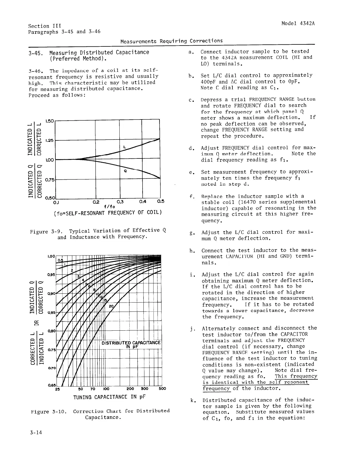
Figure 3-9.
Typical Variation of Effective Q
and Inductance with Frequency.
TUNING CAPACITANCE IN pF
Figure 3-10.
Correction Chart for Distributed
Capacitance.
a.
b.
C.
d.
e.
f.
g.
h.
1.
j.
k.
Connect inductor sample to be tested
to the 4342A measurement COIL (HI and
LO) terminals.
Set L/C dial control to approximately
400pF and AC dial control to OpF.
Note C dial reading as Cl.
Depress a trial FREQUENCY RANGE button
and rotate FREQUENCY dial to search
for the frequency at which panel Q
meter shows a maximum deflection.
If
no peak deflection can be observed,
change FREQUENCY RANGE setting and
repeat the procedure.
Adjust FREQUENCY dial control for
max-
imum Q meter deflection. Note the
dial frequency reading as fl.
Set measurement frequency to approxi-
mately ten times the frequency fl
noted in step d.
Replace the inductor sample with a
stable coil (16470 series supplemental
inductor) capable of resonating in the
measuring circuit at this higher fre-
quency.
Adjust the L/C dial control for maxi-
mum Q meter deflection.
Connect the test inductor to the
meas-
urement CAPACITOR (HI and GND) termi-
nals.
Adjust the L/C dial control for again
obtaining maximum Q meter deflection.
If the L/C dial control has to be
rotated in the direction of higher
capacitance, increase the measurement
frequency.
If it has to be rotated
towards a lower capacitance, decrease
the frequency.
Alternately connect and disconnect the
test inductor to/from the CAPACITOR
terminals and adjust the FREQUENCY
dial control (if necessary, change
FREQUENCY RANGE setting) until the in-
fluence of the test inductor to tuning
conditions is non-existent (indicated
Q value may change).
Note dial fre-
quency reading as fo.
This frequency
is identical with the self resonant
frequency of the inductor.
Distributed capacitance of the induc-
tor sample is given by the following
equation. Substitute measured values
of Cl, fo, and f~ in the equation:
3-14
 Loading...


