Edge Switch 2/24 installation guide 15
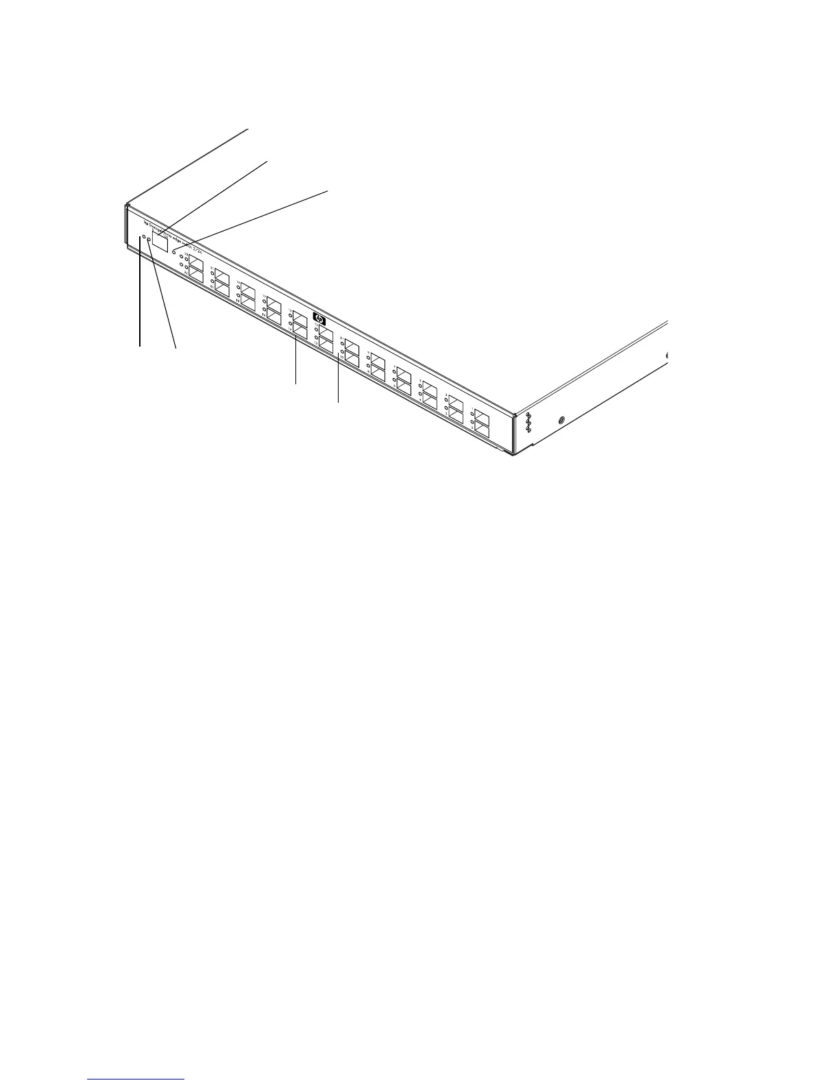
Figure 2 shows the front panel controls, connectors and indicators.
Figure 2 Edge Switch 2/24 front panel features
Power and system error LEDs
The Power LED, as shown in Figure 2, illuminates when the switch is connected to facility AC power
and powered on. If the LED extinguishes, a facility power source, power cord, or power distribution
failure is indicated.
The Error LED, as shown in Figure 2, illuminates when the switch detects an event requiring
immediate operator attention, such as a FRU failure. The LED remains illuminated as long as an
event is active. The LED extinguishes when the Clear System Error Light function is selected from the
Product Manager application.
The LED blinks if unit beaconing is enabled. An illuminated LED (indicating a failure) takes
precedence over unit beaconing. The LED also blinks (at twice the beaconing rate) when the
IML/RESET button is pressed and held for more than three seconds.
Ethernet LAN connector
The front panel provides a 10/100 megabit per second (Mbps) RJ-45 twisted-pair connector that
attaches to an Ethernet LAN to provide communication with the HAFM appliance or an SNMP
management workstation. Two green LEDs are associated with the LAN connector. When
illuminated, the left LED indicates LAN operation at 10 Mbps, and the right LED indicates LAN
operation at 100 Mbps.
1 Power LED (green)
2 Error LED (amber
3 Ethernet LAN connector
4 Initial machine load (IML) button
5 SFP fiber optic connectors
6 Port LEDs
3
1
2
4
5
6