Edge Switch 2/24 installation guide 17
Rear panel features
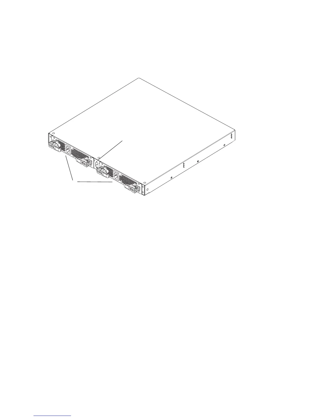
The switch provides a modular design that enables quick removal and replacement of
field-replaceable power supply assemblies with internal cooling fans. Figure 3 illustrates the rear of
the switch.
Figure 3 Edge Switch 2/24 (rear view)
Power supplies
The switch contains two power supply assemblies with internal cooling fans. The redundant,
load-sharing power supply assemblies step down and rectify facility input power to provide 3.3 volts
direct current (VDC), 5 VDC, and 12 VDC to the control processor (CTP) card. The power supplies
also provide input filtering, overvoltage protection, and overcurrent protection. An amber LED on
each assembly illuminates if the FRU fails.
Either power supply can be replaced while the switch is operational. Each power supply has a
separate connection to the CTP card to allow for independent AC power sources. The power
supplies are input rated at 90 to 264 volts alternating current (VAC).
Three cooling fans integrated in each power supply assembly (six fans total) provide cooling for the
power supplies and CTP card, as well as redundancy for continued operation if a single fan fails.
Fans are removed and replaced as part of the integrated power supply.
Power supply requirements are listed in ”Technical specifications” on page 95.
1 Power supplies with internal
cooling fans (2)
2 Maintenance port
1
2