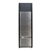
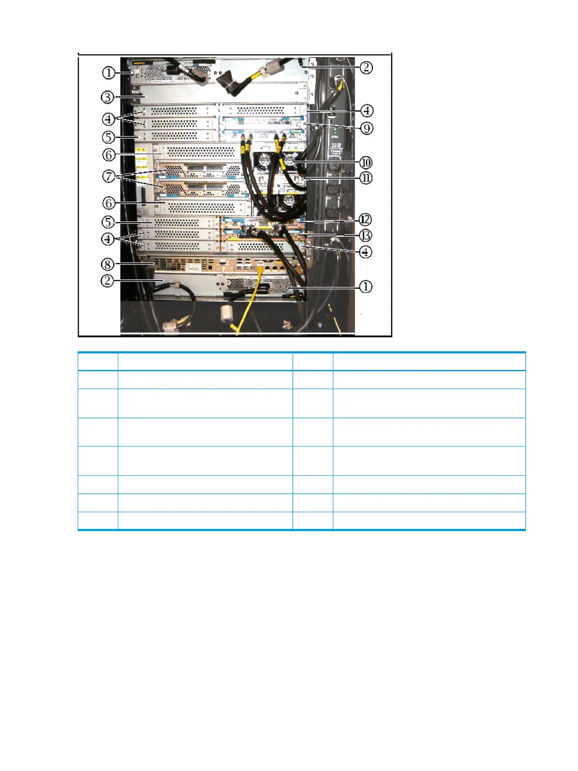
Figure 12 Controller chassis rear view (minimum configuration)
DescriptionItemDescriptionItem
Slots for optional Power Supply.2Power Supply (2 min, 4 max)1
Slots for Channel Adapter board.42
nd
Service Processor (optional for Module-0)
or Hub (optional for Module-1)
3
Slots for optional Express Switch Adapter.6Slots for optional Disk Control Adapter or
Channel Adapter board.
5
1
st
Service Processor for Module-0 or 1
st
Hub for
Module-1
8Express Switch Adapter7
Fan10Channel Adapter board9
Disk Control Adapter12SSVPMN11
--Channel Adapter board13
System control panel
The following illustration shows the HP XP7 system control panel. The table following the illustration
explains the purpose of each of the controls and LEDs on the panel.
56 System components
 Loading...