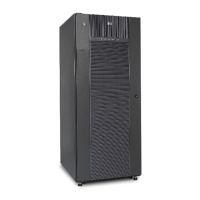
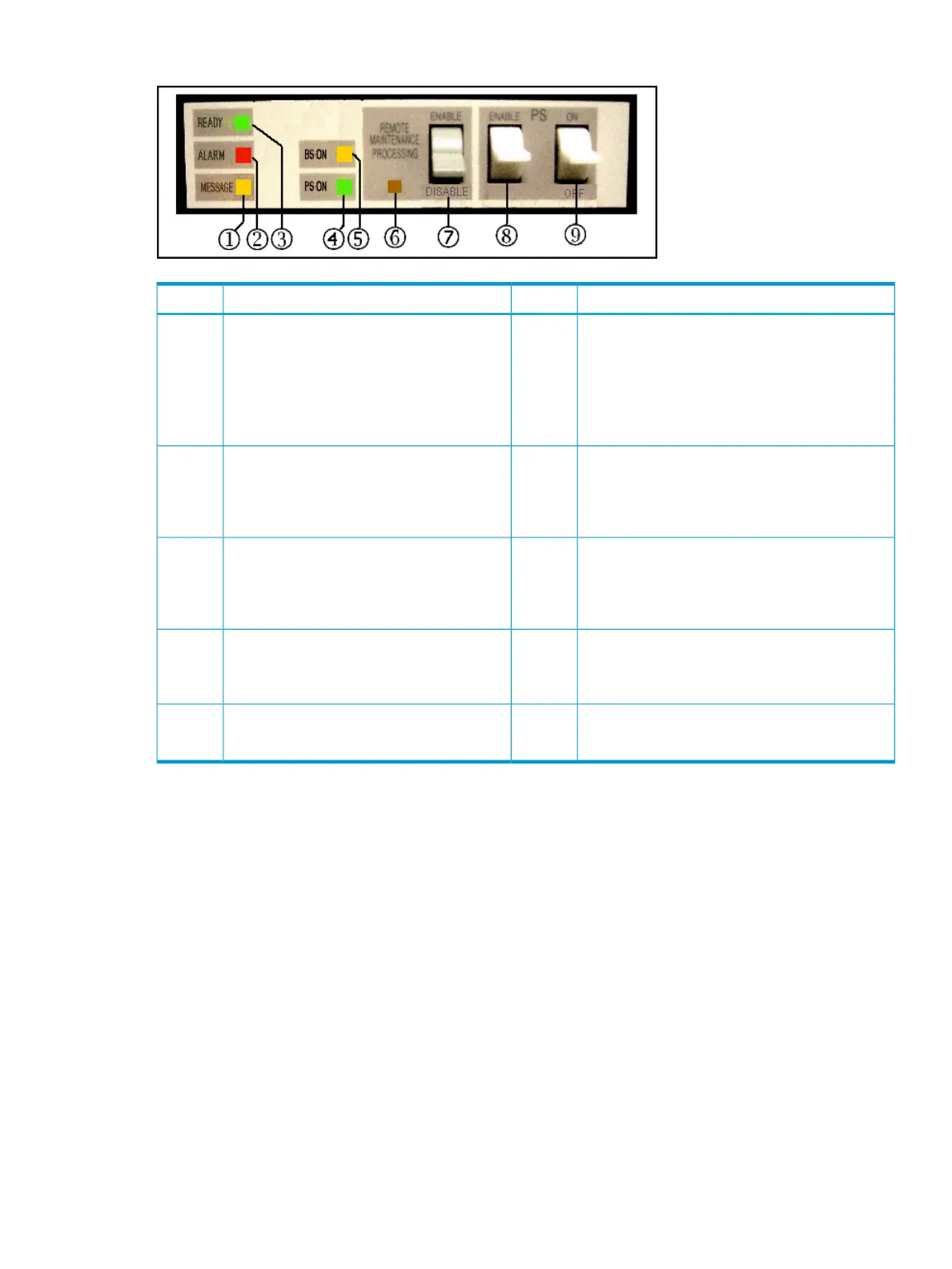
Figure 13 HP XP7 system control panel
DescriptionItemDescriptionItem
ALARM - Red LED2MESSAGE - Amber LED1
Indicates DC under voltage of any DKC part, DC
over current, abnormally high temperature, or that
an unrecoverable failure occurred.
ON: indicates that a SIM (Message) was
generated from either of the clusters. Applied
to both storage clusters.
Blinking: Indicates that a SVP failure has
occurred.
PS ON - Green LED4READY - Green LED Indicates that input/output
operation on the channel interface is enabled.
3
Indicates that the system is powered on, that the
POST is complete, and that the system has booted
up and is ready for use.
REMOTE MAINTENANCE PROCESSING - Amber
LED
6BS ON - Amber LED
Indicates that the Sub Power supply is on. (CL
1 or CL 2)
5
Indicates that the system is being remotely
maintained.
PS SW ENABLE - switch8REMOTE MAINTENANCE ENABLE/DISABLE -
switch
7
Used to enable the PS ON/PS OFF switch.
When ON, permits remote maintenance.
--PS ON/PS OFF - switch9
Turns the system power on or off.
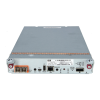
Drive chassis
The drive chassis includes two back-to-back disk drive assemblies. Each assembly includes HDDs,
SSW boards, HDD PWR boards, eight cooling fans, and two AC-DC power supplies. All components
are configured in redundant pairs to prevent system failure. All the components can be added or
replaced while the disk array is in operation.
The following illustration shows the rear view of the drive chassis. The table following the illustration
describes the drive chassis components.
Drive chassis 57
 Loading...