the rack because it is the heavier of the two units. If a system has two SVPs, both SVPs are mounted
in controller chassis #0.
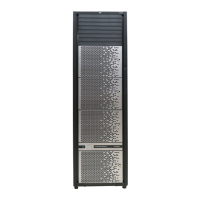
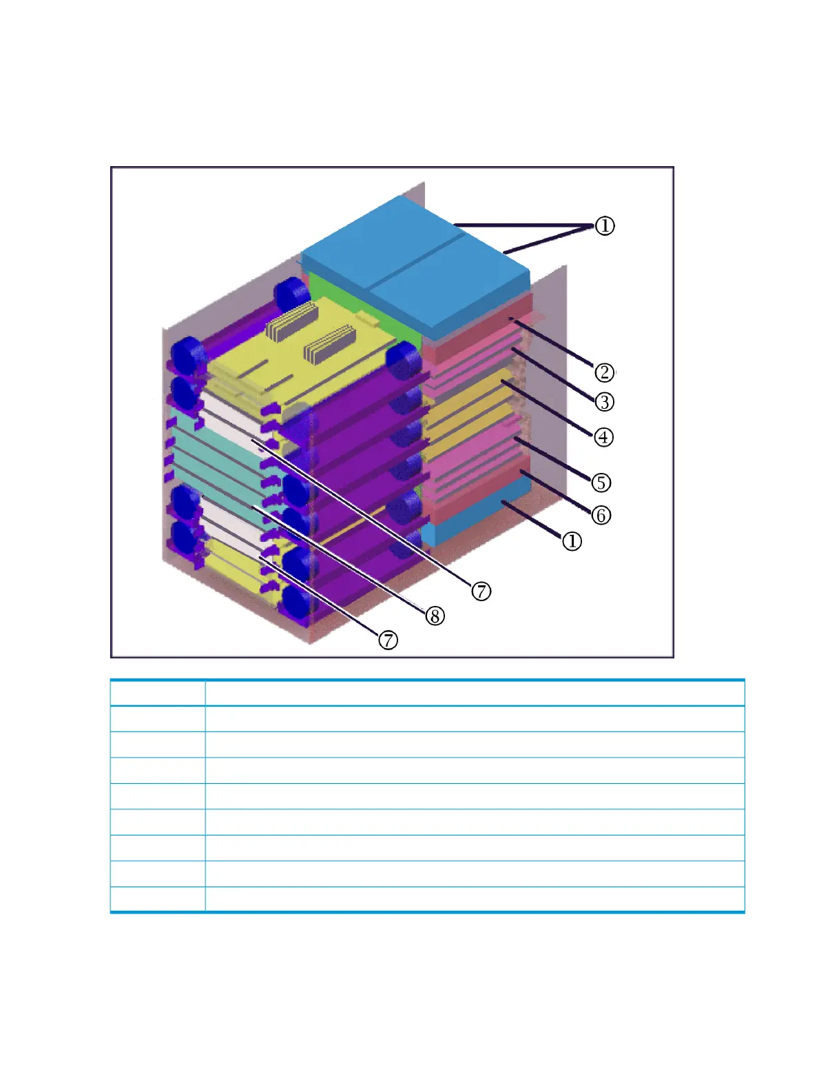
The following illustration shows the locations of the components in the controller chassis. The
controller chassis is described in more detail in “System components” (page 54).
Figure 2 Controller chassis
DescriptionItem
AC/DC: Power Supply 2 or 4 per controller1
Service Processor: One or two units in the #0 controller chassis2
CHA3
Grid switches4
CHA (up to 7) and DKA (up to 4)5
Service Processor: One or two units in the #0 controller chassis6
Cache: 2 to 8 cache boards in pairs (2, 4, 6, 8)7
HP XP7: 2 to 4 microprocessor boards8
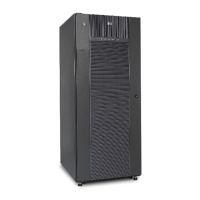
Drive chassis
The drive chassis (factory designation DKU) consists of SAS switches, slots for 2 1/2 inch, 3 1/2
inch HDD or SSD drives, and four 4 fan door assemblies that can be easily opened to allow access
to the drives. Each drive chassis can hold 128 2 1/2 inch HDD or SSD drives. The maximum
number of 2 1/2 inch drives in a HP XP7 system is 2304.
8 Introduction
 Loading...