3) Pin solder with soldering iron and absorber.
NA
4) Lift the connector up and away from the PCB.
NO
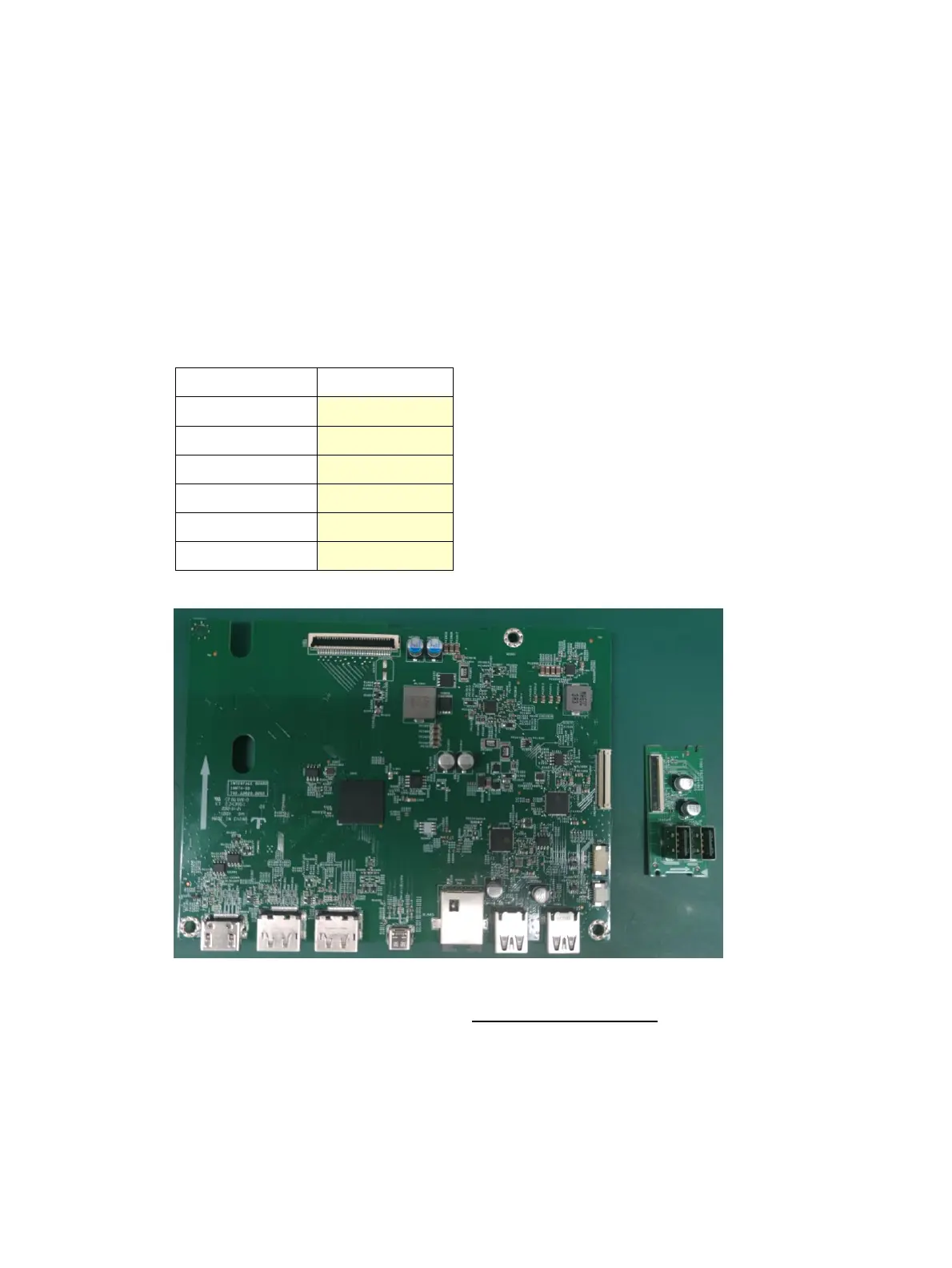
Connector repair
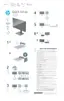
This procedure includes HDMI, Display Port, Mini Display Port, USB-C, USB-A and RJ45 connectors.
The connectors are on the main board (board part number 7ZB.A3901.0011).
The connector identifiers are as follows:
Before repairing connectors, follow these steps:
▲ Prepare the monitor for disassembly. See Preparation for disassembly on page 13.
HDMI connector HDMI1
Repair the HDMI connector:
1) Use a soldering iron and a de-soldering pump to remove as much solder as possible from the pin.
 Loading...