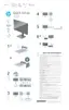
EasyManuals Logo

HP Z24U G3 User Manual

HP Z24U G3
27 pages
To Next Page IconTo Next Page
To Previous Page IconTo Previous Page
Page #24 background imageLoading...
Page #24 background image
21
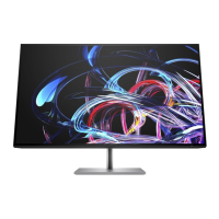
2) Lift the RJ45 connector from the PCB.
3) Place the new component on the PCB. Be sure that it matches the PCB footprint.
Solder the new component
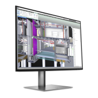
USB-A connector USB2/USB3
Repair the USB-A connector:
1) Use a soldering iron and a de-soldering pump to remove as much solder as possible from the pin.
2) Lift the USB-A connector from the PCB.
3) Place the new component on the PCB. Be sure that it matches the PCB footprint.
4) Solder the new component.
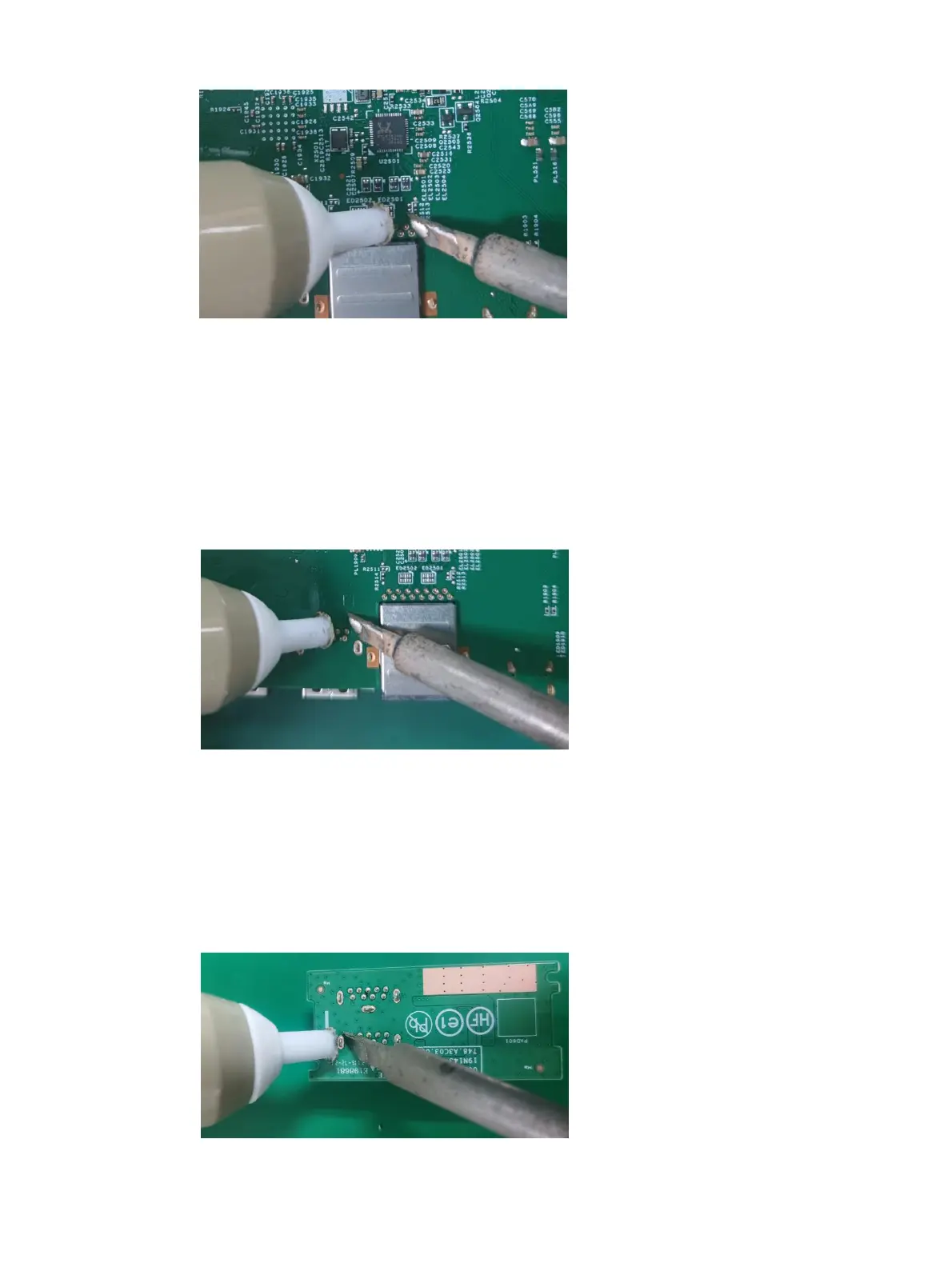
USB-A connector USB4/USB5
Repair the USB-A connector:
1) Use a soldering iron and a de-soldering pump to remove as much solder as possible from the pin.
2) Lift the USB-A connector from the PCB.

Other manuals for HP Z24U G3

Questions and Answers:

Question and Answer IconNeed help?

Do you have a question about the HP Z24U G3 and is the answer not in the manual?

HP Z24U G3 Specifications

General IconGeneral
Screen Size23.8 inches
Resolution1920 x 1200
Panel TypeIPS
Aspect Ratio16:10
Contrast Ratio1000:1
Refresh Rate60 Hz
Color Gamut99% sRGB
Viewing Angle178° horizontal, 178° vertical
AdjustabilityHeight, Tilt, Swivel, Pivot
Response Time5ms
Ports1 x DisplayPort 1.4, 1 x USB-C
VESA Mount100 x 100 mm
Brightness300 cd/m²
Pixel Pitch0.2745 mm

Related product manuals