9
Figure 8 Connecting the grounding cable to the grounding strip
Grounding the switch with a grounding conductor buried in
the earth ground
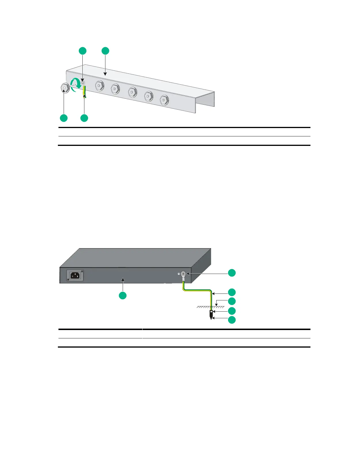
If the installation site has no grounding strips, but earth ground is available, hammer a 0.5 m (1.64 ft)
or longer angle iron or steel tube into the earth ground to serve as a grounding conductor.
The dimensions of the angle iron must be a minimum of 50 × 50 × 5 mm (1.97 × 1.97 × 0.20 in). The
steel tube must be zinc-coated and its wall thickness must be a minimum of 3.5 mm (0.14 in).
Weld the yellow-green grounding cable to the angel iron or steel tube and treat the joint for corrosion
protection.
Figure 9 Grounding the switch by burying the grounding conductor into the earth ground
Grounding the switch by using the AC power cord
If the installation site has no grounding strips or earth ground, you ground an AC-powered switch
through the PE wire of the power cord. Make sure of the following information:
The power cord has a PE terminal.
The ground contact in the power outlet is securely connected to the ground in the power
distribution room or on the AC transformer side.
The power cord is securely connected to the power outlet.

 Loading...


