24
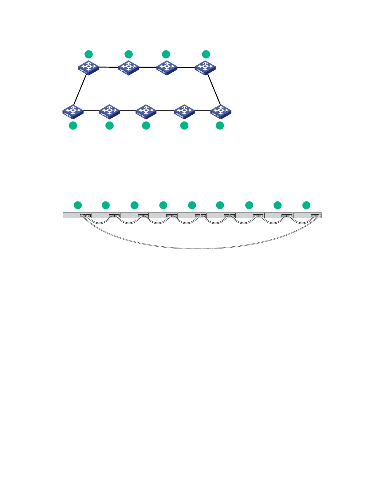
Figure 24 IRF fabric topology
Connecting the IRF member switches in a ToR solution
You can install IRF member switches in different racks side by side to deploy a top of rack (ToR)
solution.
Figure 25 shows an example for connecting 9 top of rack IRF member switches by using SFP+
transceiver modules and optical fibers. The topology is the same as Figure 24.
Figure 25 ToR cabling
Configuring basic IRF settings
After you install the IRF member switches, power on the switches, and log in to each IRF member
switch (see HPE OfficeConnect 1950 12XGT 4SFP+ Switch (JH295A) User Guide) to configure their
member IDs, member priorities, and IRF port bindings.
Follow these guidelines when you configure the switches:
Assign the master switch higher member priority than any other switch.
When connecting two neighboring IRF member switches, you must connect the physical ports
of IRF-port 1 on one switch to the physical ports of IRF-port 2 on the other switch.
For more information about configuring basic IRF settings, see HPE OfficeConnect 1950 12XGT
4SFP+ Switch (JH295A) User Guide.
Connecting the physical IRF ports
Use twisted pair cables, SFP+ network cables, or SFP+ transceiver modules and fibers to connect
the IRF member switches as planned.
Wear an ESD wrist strap when you connect SFP+ network cables or SFP+ transceiver modules and
fibers. For how to connect them, see HPE SFP/SFP+/XFP Transceiver Modules and Network Cables
Installation Guide.
 Loading...


