Chapter 6 Function Introduction Shenzhen Hpmont Technology Co., Ltd
―94― HD30 Series Inverters User Manual
No. Name Description Range
factory setting
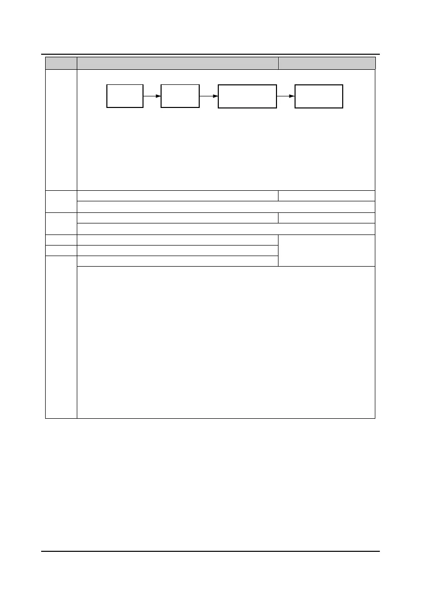
analogue input and the setting frequency is shown as figure:
The analogue voltage reasults from setting frequency signal disposed by analogue input filtering, bias
and gain. The relationship between the analogue voltage and the setting frequency is set by
parameters of Group F05.
It defines the filtering constant. It is used to filter the analogue signal.The bigger the constant, the
higher the immunity level, but the response time is prolonged with the increase of this constant. That
is, the smaller the constant, the shorter the response time, but the lower the immunity level.
Note: Only when using HD30-EIO will F16.11
F16.16 (analogue inputs AI3 and AI4) be
enabled.
Maximum input pulse frequency
When set the DI6 terminal as pulse input, F16.17 defines the maximum input pulse frequency.
Input pulse filtering time
It is used to filter the input pulse frequency and filter out the small fluctuations in the pulse frequency.
AO1 terminal output function selection
0
19
0
F16.20 AO2 terminal output function selection
High-speed pulse output function selection
0: Reversed.
1,2: Output frequency, reference frquency (0-maximum output frequency)
3: Motor speed (0-maximum output frequency corresponding to speed).
4: Output current (0-twice motor’s rated current).
5: Output current (0-twice motor’s rated current).
6-9: Reversed.
10: Output torque (0-3 times motor’s rated torque).
11: Output voltage (0-1.2 times inverter’s rated voltage).
12: Bus voltage (0-2.2 times inverter’s rated voltage).
13: Output power (0-twice motor’s rated power).
14: AI1 input (0-10V).
15: AI2 input (-10-10V / 0-20mA).
16: AI3 input (-10-10V / 0-20mA).
17: AI4 input (-10-10V / 0-20mA).
18,19: Output frequency, reference frequency (- 1 times-1 times maximum output frequency).
Analogue
actual value
Analogue
input filtering
Analogue input gain
Analogue input bias
Analogue value
after computing

 Loading...


