Shenzhen Hpmont Technology Co., Ltd Chapter 4 Electrical Installation
HD30 Series Inverters User Manual ―21―
4.4 Meet EMC Requirement of Installation
4.4.1 Correct EMC Installation
According national standards GB/T12668.3, the inverter should meet the two requirements of
electromagnetic interference (EMI) and anti-electromagnetic interference. The international
standards IEC/61800-3 (VVVF drive system part 3: EMC specifications and test methods) are
identical to the national standards GB/T12668.3.
HD30 Series Inverters are designed and produced according to the requirements of IEC/61800-3.
Please install the inverter as per the description below so as to achieve good electromagnetic
compatibility (EMC).
Divide the installation space into different areas:
In a drive system, the inverter, control equipment and sensors are installed in the same cabinet,
the electromagnetic noise should be suppressed at the main connecting points with the EMI filter
and input reactor installed in cabinet to satisfy the EMC requirements.
The most effective but expensive measure to reduce the interference is to isolate the noise
source and the noise receiver, which should be considered in mechanical system design phase.
In driving system, the noise source can be inverter, braking unit and contactor. Noise receiver can
be automation equipment, encoder and sensor etc.
The mechanical/system is divided into different EMC areas according to its electrical
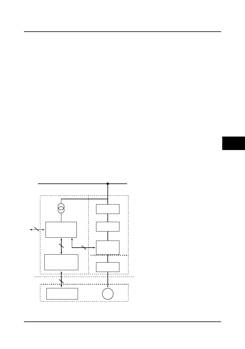
characteristics. The recommended installation positions are shown in Figure 4-5.
Figure 4-5 System wiring sketch
HD30 inverter
EMI filter
Mechanical system
EMI filter
ACreactor
Manufacture machines
Area E
Area A: install transformers of control power supply,
control devices and sensor etc.
Power supplycontrol cabinet
Area C
Area A
Area B
Area D
Area F
Motor
Sensor (temperature,
liquidlevel sensor)
Control devices (the
host PC, PLCetc.)
Area B: interfaces of signal and control cables,
correct immunity level is required.
Area C: install noise sources such as input reactor,
the inverter, braking unit and contactor.
Area D: install output EMI filterand itscable
connection p
arts.
Area E: power supply.
Area F: install motor and its cables.
Earth isolatedboard
4

 Loading...


