Shenzhen Hpmont Technology Co., Ltd Chapter 6 Function Introduction
HD30 Series Inverters User Manual ―71―
6.2.8 Group F07 Wobble Operation Parameters
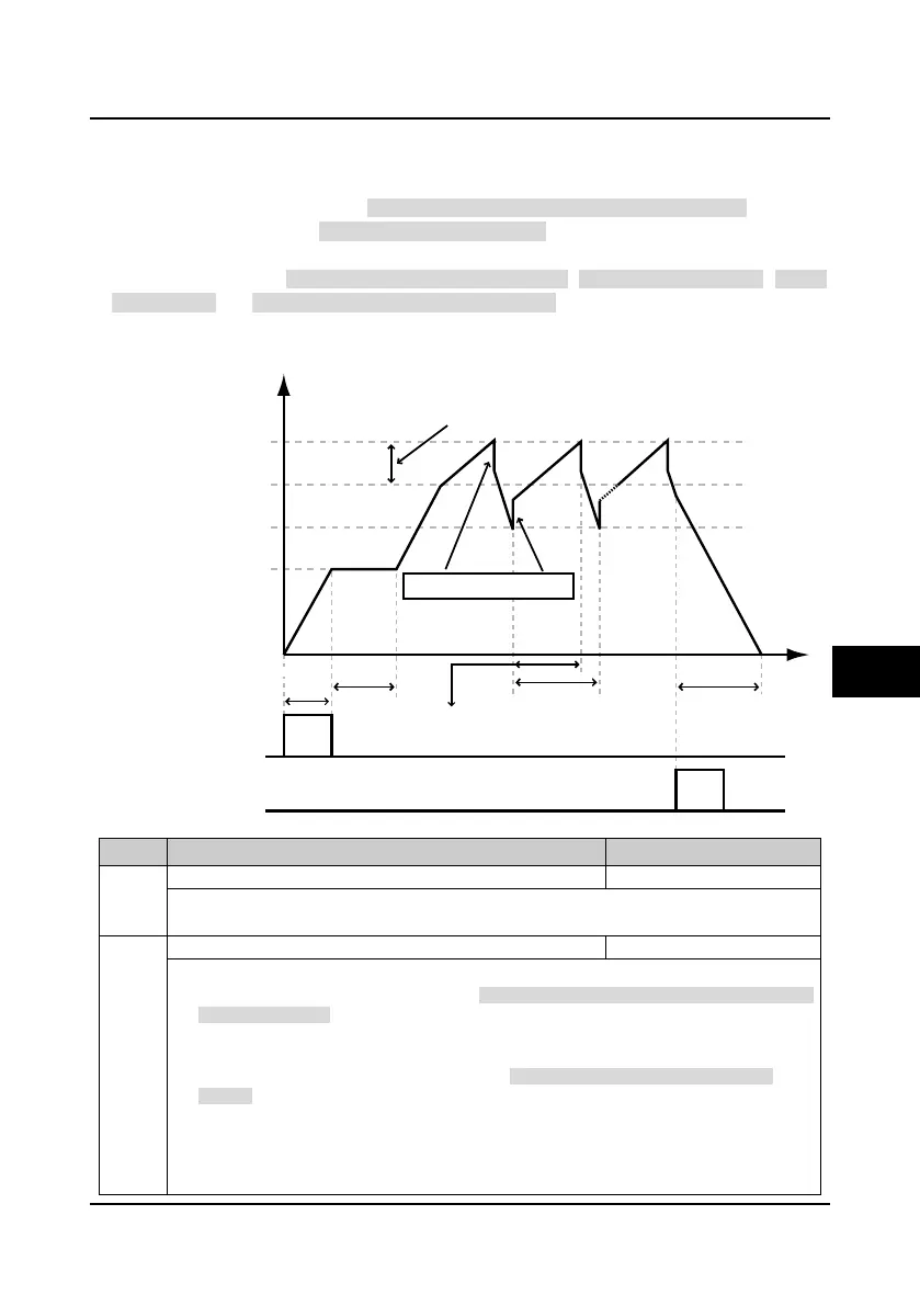
The wobble operation process is shown as below:
First, the inverter accelerates to the preset frequency of wobble operation (F07.02) within the
acceleration time and then waits for certain time (F07.03). Hinterher the inverter transits to the
central frequency of the wobble operation as per the acceleration time, and ultimately start wobble
operation according to the preset wobble amplitude (F07.04), jump frequency (F07.05), wobble
cycle (F07.06) and the rise time of wobble operation (F07.07) until it receives a stop command and
stops as per the deceleration time.
The process is shown in figure:
No. Name Description Range
factory setting
Wobble operation selection
0: Disabled.
1: Enabled.
Units: Start mode of wobble operation.
• 0: Auto start. The inverter will first operate at the preset frequency of wobble operation (F07.02) for
certain time (F07.03), and then enter wobble mode automatically.
• 1: Manual start. If the multi-function terminal is set as No.36 function (set as wobble start function)
and the signal is enabled, the inverter will enter wobble mode. If the terminal is disabled, the
inverter will end wobble operation and operate at the preset frequency of wobble operation
(F07.02).
Tens: Wobble operation amplitude. Refer to parameter F07.04.
• 0: Relative to the wobble central frequency.
• 1: Relative to the maximum output frequency.
F07.03
Acc.
time
F07.06
Dec.time
Rising time: F07.06 x F07.07
F07.02
Running frequency
Lower limit of frequency F
L
Central frequency F
set
Upper limit of frequency F
H
F
H
= F
set
+ F
w
F
L
= F
set
- F
w
Amplitude F
w
= Fset x F07.04
Jump freq. = F
w
x F07.05
Run command
Stop command
Time
6

 Loading...


