Shenzhen Hpmont Technology Co., Ltd Chapter 6 Function Introduction
HD30 Series Inverters User Manual ―73―
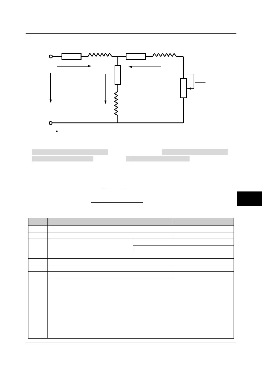
6.2.9 Group F08 Asynchronous Motor 1 Parameters
The idling exciting current (F08.11) can be calculated by the motor’s rated current (F08.02) and
motor’s power factor (F08.05) or detected by motor auto-tuning (F08.06 = 2).
The relationship between rated torque current, idling exciting current and motor’s rated current is
below:
Rated torque current = F08.05 × F08.02
Idling exciting current F08.11 =
�
1 − F08.05
2
× F08.02
Mutual inductance F08.10 =
F08.01
2
√
3
π × F08.03 × F08.11
− F08.09
Note: Except F08.03, F08.04 and F08.06, the other factory settings are depended on the inverter’s model.
No. Name Description Range
factory setting
F08.00 Rated power of motor 1 0.2
500.0kW
0-inverter’s rated voltage
F08.02 Rated current of motor 1 5.5kW above 0.0
999.9A
F08.03 Rated frequency of motor 1 1.0
400.0Hz
50.0
F08.05 Power factor of motor 1 0.001
1.000
Parameter auto-tuning of motor 1
0: Auto-tuning is disabled.
1: Stationary auto-tuning.
• In the process of stationary auto-tuning, the motor is at rest. The stator resistance, rotor
resistance and leakage inductance will be measured and written into F08.07, F08.08 and
F08.09 automatically.
2: Rotary auto-tuning.
• In process of rotary auto-tuning, the motor is at rest at the beginning, and the stator resistance,
rotor resistance and leakage inductance will be measured. Hinterher the motor will start
rotating, accordingly mutual inductance and idling exciting inductance will be measured
automatically. All the measured values above will be saved respectively in F08.07, F08.08,
I1
I2
Io
R1 R2Ll Ll
L
m
U1
R2
1 - S
S
R1 = F08.07 (Stator resistance) Ll = F08.09 (Leakage inductance)
R2 = F08.08 (Rotor resistance) Lm = F08.10 (Mutual inductance)
Io = F08.11 (Idling exciting current) S = Slip ratio
6

 Loading...


