Chapter 4 Electrical Installation Shenzhen Hpmont Technology Co., Ltd
―28― HD30 Series Inverters User Manual
4.5.2 Wire Jumper Description
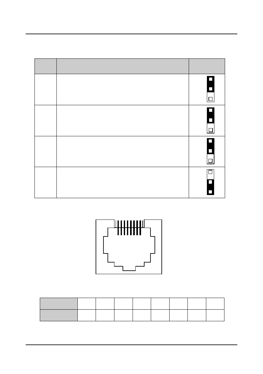
Table 4-5 HD30 wire jumper function and setting description
Jumper
switch
Function and setting description Factory setting
CN6
AI2 analogue input channel can select voltage or current signal. When
pin 1 and pin 2 of the CN6 are short-circuited, AI2 channel inputs
voltage signal; when pin 2 and pin 3 of the CN6 are short-circuited, AI2
channel inputs current signal.
CN7
AO1 analogue output channel can select voltage or current signal.
When pin 1 and pin 2 of the CN7 are short-circuited, AO1 channel
outputs voltage signal; when pin 2 and pin 3 of the CN7 are
short-circuited, AO1 channel outputs current signal.
CN8
AO2 analogue output channel can select voltage or current signal.
When pin 1 and pin 2 of the CN8 are short-circuited, AO2 channel
outputs voltage signal; when pin 2 and pin 3 of the CN8 are
short-circuited, AO2 channel outputs current signal.
CN9
SCI communication can select proper resistance. When pin 2 and pin
3 of the CN9 are short-circuited, no resistance; when pin 1 and pin 2
of the CN9 are short-circuited, select the proper resistance.
4.5.3 SCI Communication Terminal Description
Figure 4-14 SCI communication terminal
Table 4-6 SCI communication terminal description
Communication
1 2 3 4 5 6 7 8
Communication
+5V 485+ +5V GND GND GND 485- Reserved

 Loading...


