Shenzhen Hpmont Technology Co., Ltd Chapter 6 Function Introduction
HD30 Series Inverters User Manual ―55―
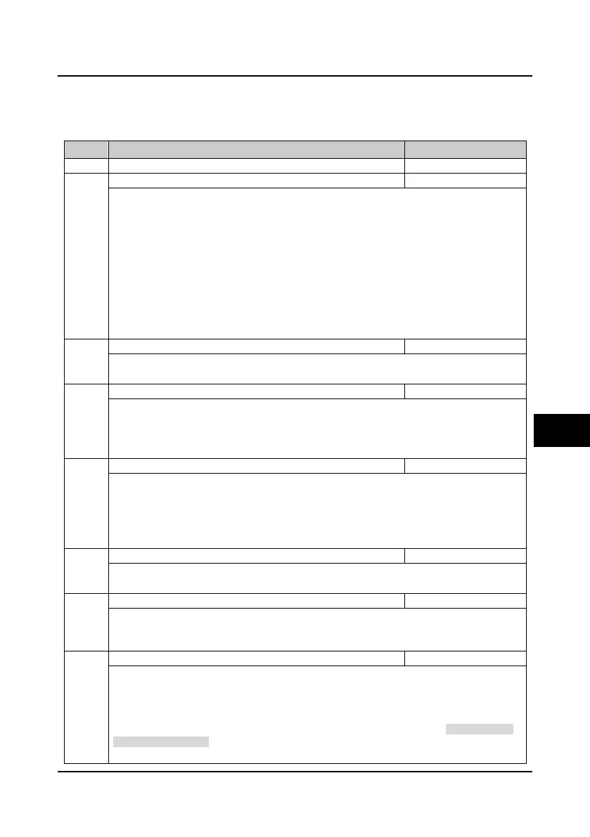
6.2 Group F: General Function Parameters
6.2.1 Group F00 Basic Parameters
No. Name Description Range
factory setting
F00.01 Motor 1 control mode selection 0
2
0
0: V/f control without PG. Constant voltage/frequency ratio control.
• It is specially applicable for occasions when one inverter drives more than one motors to
achieve proper efficiency.
• When select V/f control, please properly set the V/f control parameter of Group F09 or Group
F13 to achieve proper efficiency.
1: Reserved.
2: Vector control without PG. Sensorless vector control.
• It is applicable for application with high requirement on inverter performance and torque.
• At first, it must perform motor parameter auto-tuning. And then adjust the settings of F08.00-
F08.04 according to the nameplate of the motor. Start the motor parameter auto-tuning function
and properly set Group F10 parameters, so as to achieve excellent vector control efficiency.
F00.02 Inverter type setting 0,1
0
0: G type, to drive heavy and general motor.
1: P type, to drive pump and fan.
F00.03 Motor selection 0,1
0
0: Motor 1.
1: Motor 2.
Note: It can preset two group motor parameters. At stop they can shift even without input
parameters when they are respectively driving two motors.
F00.04 HD30 general extension option selection 0
3
0
0: Option is invalid.
1: HD30-EIO is valid.
2: HD30-WIO is valid.
3: HD30-PIO is valid.
Note: The extension function can be used with the corresponding option.
F00.05 HD30 extension application function 0,1
0
0: No extension application.
1: Water and wastewater applications.
F00.06 Inverter maximum output frequency 50.00
400.00Hz
50.00
It defines the highest frequency that the inverter is allowed to output.
• It should be careful to set reasonable parameters according to the nameplate of the motor and the
actual operating conditions.
F00.07 Upper limit of operation frequency setting source 0
2
0
It defines the highest frequency that the user is set to operate, and select different setting sources to
set the upper limit frequency by F00.07.
0: Digital setting. Set the upper limit frequency by F00.08.
1: Analogue input AI setting. See Group F16.
2: Terminal pulse setting. F16.17 sets the max. pulse input frequency according to F00.06 (inverter
max. output frequency).
6

 Loading...


