Chapter 4 Electrical Installation Shenzhen Hpmont Technology Co., Ltd
―20― HD30 Series Inverters User Manual
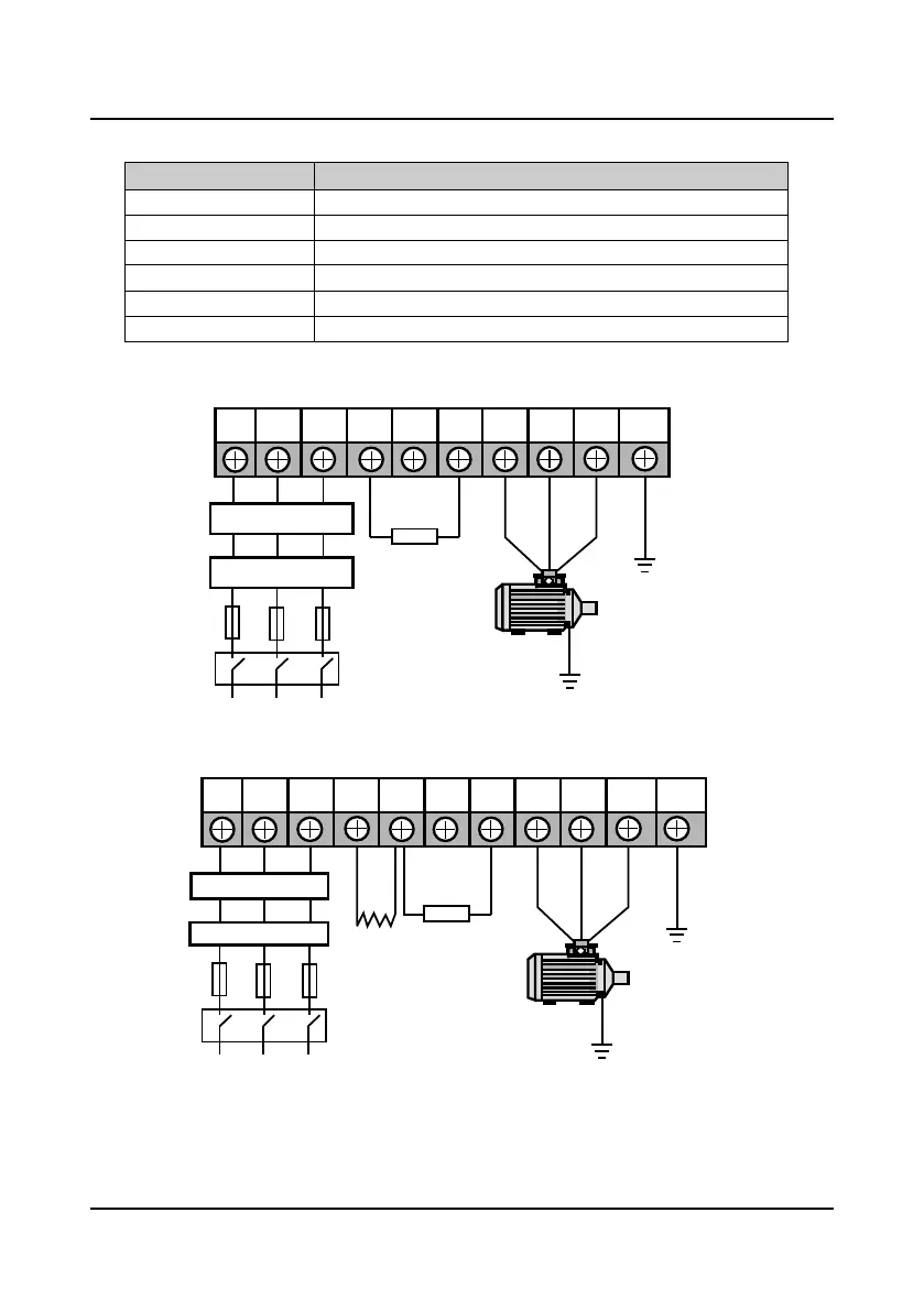
Table 4-2 HD30 main circuit terminal function description
Terminal Function Description
L1、L2、L3 Three-phase AC power input terminals
U、V、W Output terminals, connect to three-phase AC motor
P1、( +) DC reactor connection terminals
(+)、( -) DC supply input terminals; External braking unit connection terminals.
(+)、 BR Braking resistor connection terminals
PE Earth terminal, connect to the ground
4.3.2 Wiring Terminals
Figure 4-3 Main circuit connection of 5.5KW or below model
Figure 4-4 Main circuit connection of 7.5-55KW model
During trial operation, make sure the inverter runs forward when the forward command is enabled.
If not, switch any two of the output terminals (U, V, W) or modify the setting of parameter F00.17
to change the inverter’s direction.
L1 L2 L3 (+) (-) BR U V W PE
Optional EMI filter
Optional AC reactor
Fuses
Braking resistor
Mains supply
Supply ground
L1 L2 L3 (+) (-) BR U V W PEP1
Optional EMI filter
Optional AC reactor
Mains supply
Braking resistor
Fuses
DC reactor
(external)
Supply ground

 Loading...


