Appendix C Communication Protocol Shenzhen Hpmont Technology Co., Ltd
―158― HD30 Series Inverters User Manual
MODBUS adopts “Big Endian” encoding mode, higher byte prior to lower byte at sending.
1. RTU mode
In the RTU mode, the idle time of frame head and frame tail passing bus should be not less than
3.5 bytes, and data checking relies on CRC-16. The whole information need be checked. The
concrete CRC checking is referred to the page 168.
Take RTU data for example: To read internal register F00.08 of No. 1 inverter:
The command frame:
Address Parameter Register Address Read char no. Checksum
0x01 0x03 0x00 0x08 0x00 0x01 0x5 0xc8
The response frame:
Address Parameter Response Byte
Content of register Checksum
0x01 0x03 0x02 0x13 0x88 0xB5 0x12
2. ASCII mode
In ASCII mode, the frame head is “0x3A”, while the frame tail default is “0x0D”“0x0A” and the
frame tail can be set by the users. In ASCII mode, all the data bytes will be sent via ASCII code
except frame head and frame tail, higher 4-byte prior to lower 4-byte at sending. In ASCII mode,
data is 7-byte and for the “A”
-
“F” will adopt their uppercase of the ASCII code. The data adopts
LRC checking, covering the slave address and data. Checksum is the character of data that is
involved in checking and the complement code of carry bit.
Take ASCII data for example: To write 4000 (0x0FA0) to the internal register F00.08 of Slave 1.
LRC checking = the complement code of (0x01+0x41+0x00+0x08+0x0F+0xA0) =0x07
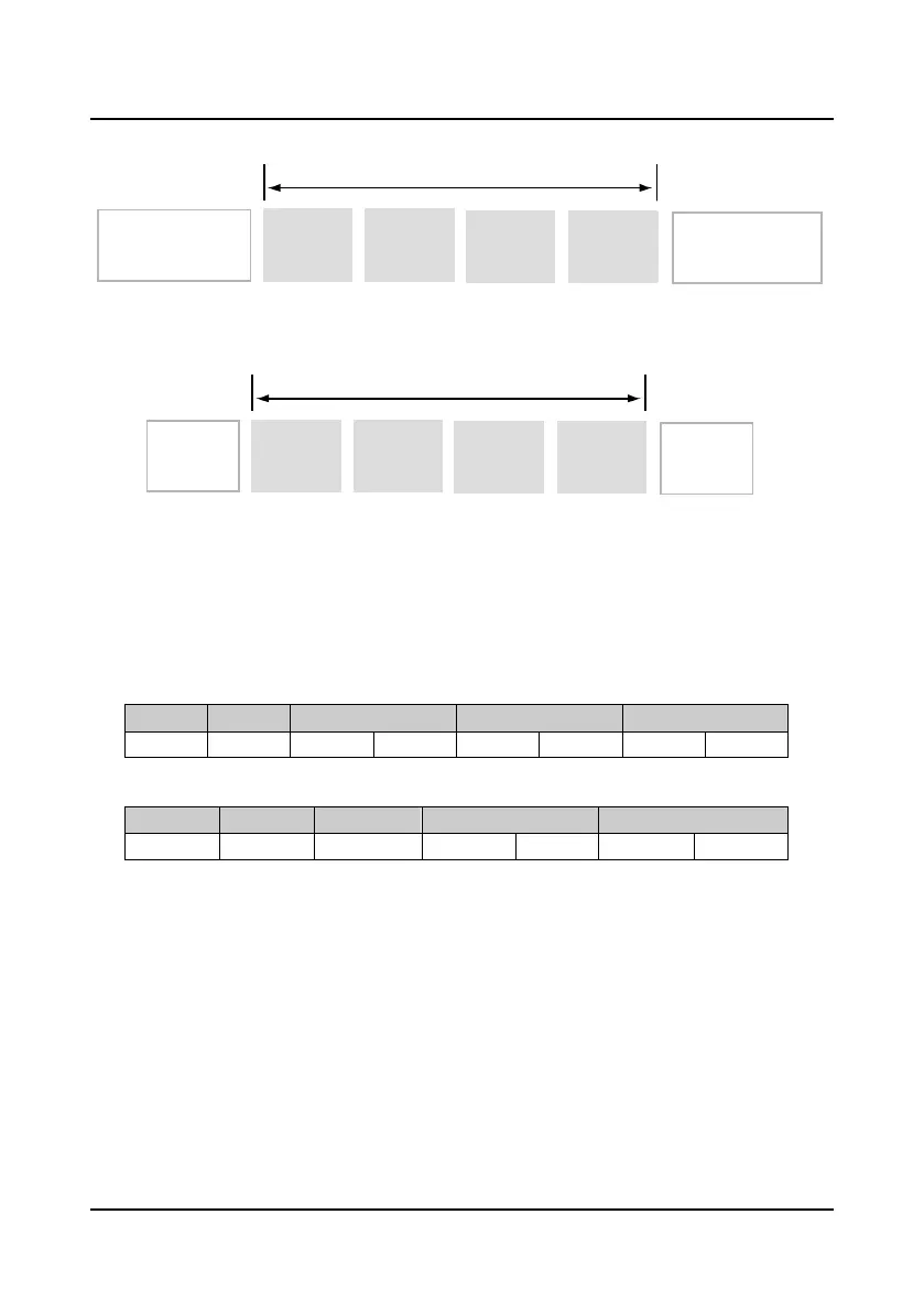
Slave
address
Frame head (at least
3.5character spacing)
Function
parameter
Data
Checking
Modbus dataframe
Frame tail (at least
3.5character spacing)
Frame head
Frame tail
Data
Checking
Modbus dataframe
ASCII mode
(0x0D,0x0A)
(0x3A)
Slave
address
Function
parameter
 Loading...


