Chapter 6 Function Introduction Shenzhen Hpmont Technology Co., Ltd
―66― HD30 Series Inverters User Manual
No. Name Description Range
factory setting
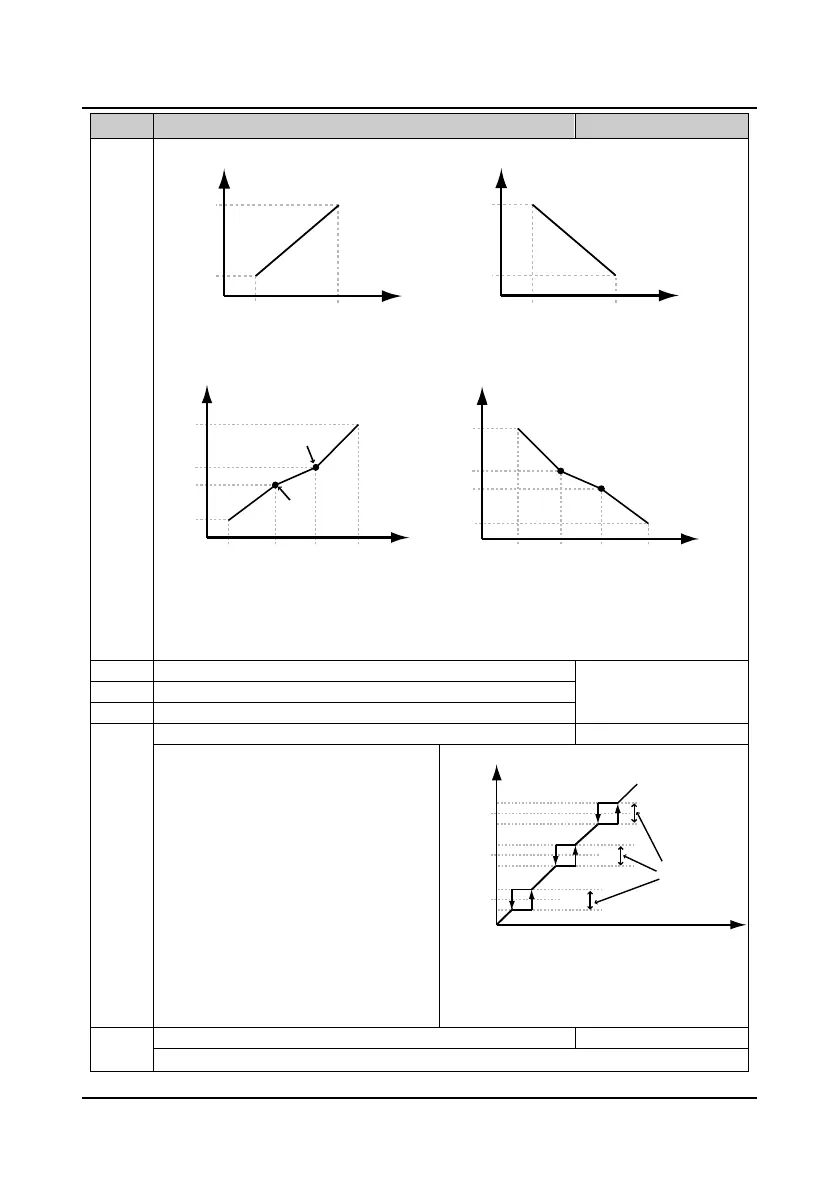
In the figure:
• P/A is terminal pulse/ analogue reference.
• Pulse frequency P is 100% corresponding to F16.17 maximum input pulse frequency.
• Analogue input value (A) is 100% corresponding to 10V or 20mA.
F05.17 Skip frequency 1 F00.09
upper limit
0.00Hz
F05.19 Skip frequency 3
The setting of skip frequency is for the
inverter’s output frequency to avoid resonant
with the load.
• The inverter will skip the above frequencies
as shown in figure. Up to 3 skip frequency
ranges can be set.
• During the process of acceleration/
deceleration, the inverter will run with
countinous frequency output, ignoring the
skip frequency ranges. But the inverter will
not run at constant speed in the skip
frequency ranges.
• Frequency setting is uncontinuous, while
frequency output is continuous.
Jog operation frequency digital setting 2
When select jog operation 2 through terminal, set the jog frequency operation according to F05.21.
Reference corresponding value
P/A(reference)
F05.01
F05.05
F05.03
F05.07
F05.04
F05.08
F05.02
F05.06
Positive and negative characteristics of line
F05.01
F05.05
F05.03
F05.07
F05.02
F05.06
F05.04
F05.08
P/A(reference)
Reference corresponding value
F05.09
F05.16
F05.15
F05.13
F05.11
F05.14
F05.12
F05.10
Inflection point 2
F05.15
F05.10
F05.12
F05.14
F05.16
F05.13
F05.11
F05.09
Reference corresponding value
Reference corresponding value
Positive and negative characteristics of polyline
P/A(reference)
P/A(reference)
Inflection point 1
Inflection point 2
Inflection point 1
Setting frequency after adjusted
F05.17
F05.18
F05.19
Skip range
Setting frequency

 Loading...


