MONT30 Starting Guide V1.0
6
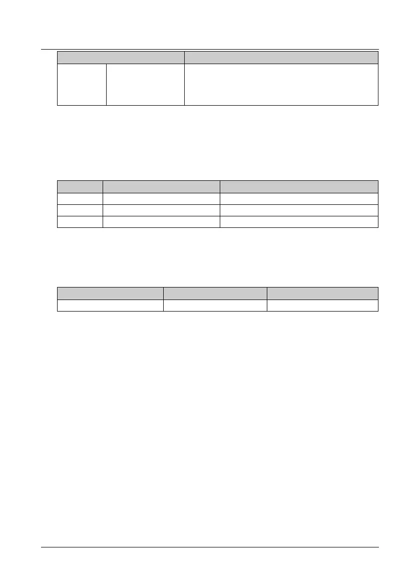
Encoder Terminal Description
CS, CK ,SO
Absolute encoder
signal
SPI communication
•
CS: Chip select input, low level is valid
•
CK: Clock input
•
SO: Data output
3.2 Controller Wiring
3.2.1 Confirm the OD and CD Mode (Distance or Speed Control)
Different motors, different control modes, and different wiring modes.
Tabl e 3-4 Confirm the OD and CD mode
Motor Detect Door Position Door Control (F00.02)
Syn. Encoder Distance control F00.02 = 1
Asyn. Encoder Distance control F00.02 = 1
Asyn. 4 travel switches Speed control F00.02 = 0
3.2.2 Select Power Cable
See the table below for recommended cable diameters.
The ground cable diameter must accord with the requirement in 4.3.5.4 of IEC 61800-5-1.
Tabl e 3-5 Power cable diameter selection
Power Cable (mm
2
) Motor Cable (mm
2
) Ground Cable (mm
2
)
0.75 0.5 2.5
3.2.3 Wiring Requirements
•
The specification of the control cable is 18AWG.
•
The length of the control cable is less than 50m, and the distance from the motor cable
is more than 0.3m, which can decrease the interference of the control signal.
•
The control cables must use shielded cables.
•
The communication cable must use a shielded twisted pair with a twisted wire pitch of
20 - 30mm, and the shielding layer is grounded.
•
The encoder must use shielded cable, and the shielding layer must be grounded
reliably at one end.
 Loading...
