8 Replacing components
98
HSD S.p.A. © - 0108h02a.fm100713
visually verify that the gear wheel does not touch the reader when the shaft rotates,
follow the procedure for assembling the shaft kit in reverse.
Perform the sensor calibration procedure:
8.4 Replacement and adjustment of the sensor unit
8.4.1 Access to sensors
To access the sensor compartment lift the cover after having unscrewed the 4 screws that lock it
The adjustment of the sensors in model ES327 occurs by moving the sensor axially in relation to
the electrospindle; while with models ES330 and ES370 the adjustment occurs by rotating the
sensor unit and taking advantage of the eccentricity of the nut that contains it.
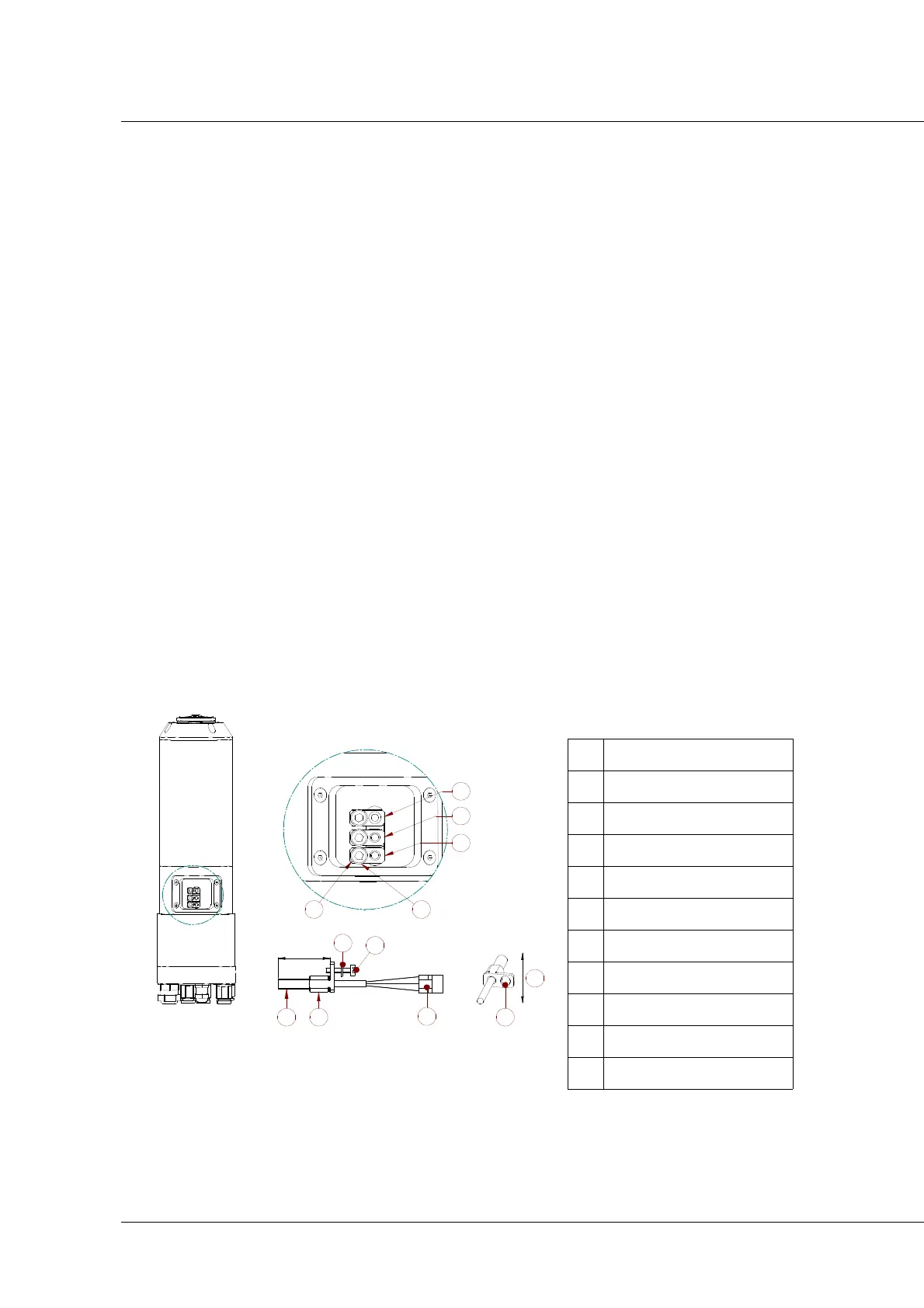
8.4.2 Identification and description of the sensor unit
ES327
Figure 12
S1 sensor S1
S2 sensor S2
S3 sensor S3
1 Screw
2 Washer
L Calibrated position
3 Sensor
4 nut
5 Electric connector
6 Slot with clearance
7 Calibration movement