5 Installation and commissioning
HSD S.p.A. © - h0104k02a.fm091115
47
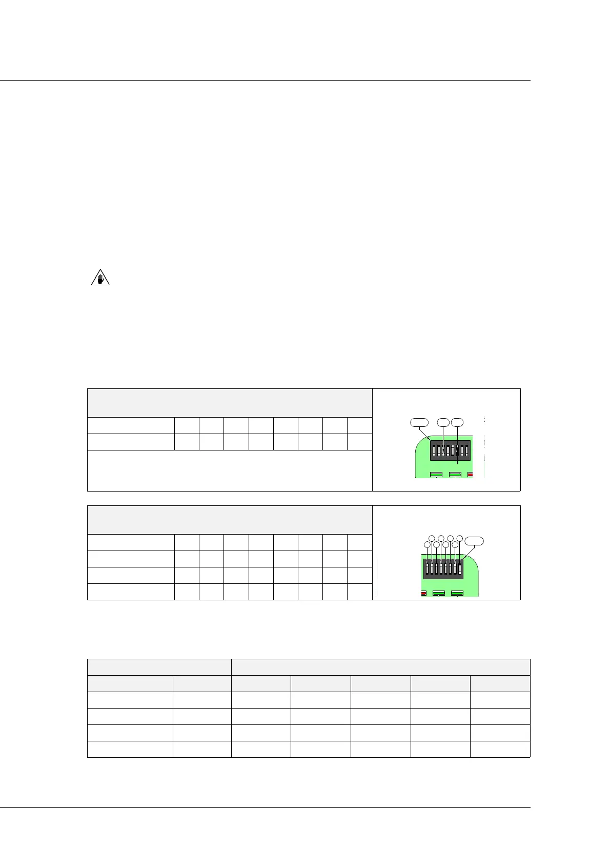
5.8.1 E-NETx configuration
The five dip-switches are used to set the electronic drive Fieldbus address. To set the drive
address, enable the dip-switches in such a way that the binary number corresponds to the
required address. Bear in mind that the less important address corresponds to A0, and the most
important corresponds to A4. Dip-switches 3 and 4 (DSW1) are used to end the line (necessary to
prevent signal reflection on the line). If the device is the last connected module on the serial line,
dipswitches 3 and 4 must both be ON. For the other line modules, dipswitches 3 and 4 must both
be OFF (module not terminated).Refer to the user manual "Technical characteristics and E-NETx
connection” (for the E-NETx communication protocol) issued by HSD S.p.A. to have more
information on how to end the line correctly.
If dipswitches 3 and 4 are set differently (for example 3 ON and 4 OFF), the module
will not work correctly.
Logical address and E-NETx bus line termination
Access the Dipswitches of the E-NETx device board as described on page 46.
Examples:
DSW1
Enet-X protocol selection
Switch 12345678
Position On On TTOffOffOn On
T = Fieldbus line termination:
set Off if the Fieldbus continue,
set On at the Bus termination.
DSW2*
Device address
*
The address is the sum of the Address Bits A0-A4 values.
Switch 12345678
Address Bits A0 A1 A2 A3 A4 Off Off Off
Value if OFF 00000OffOffOff
Value if ON 1 2 4 8 16 Off Off Off
ADDRESS DIP-SWITCH SETTING
Decimal Binary A4 A3 A2 A1 A0
01 00001 OFF OFF OFF OFF ON
05 00101 OFF OFF ON OFF ON
10 01010 OFF ON OFF ON OFF
21 10101 ON OFF ON OFF ON