5 Installation and commissioning
HSD S.p.A. © - h0104k02a.fm091115
33
More useful information on fixing can be found in the appendix A “Technical characteristics”.
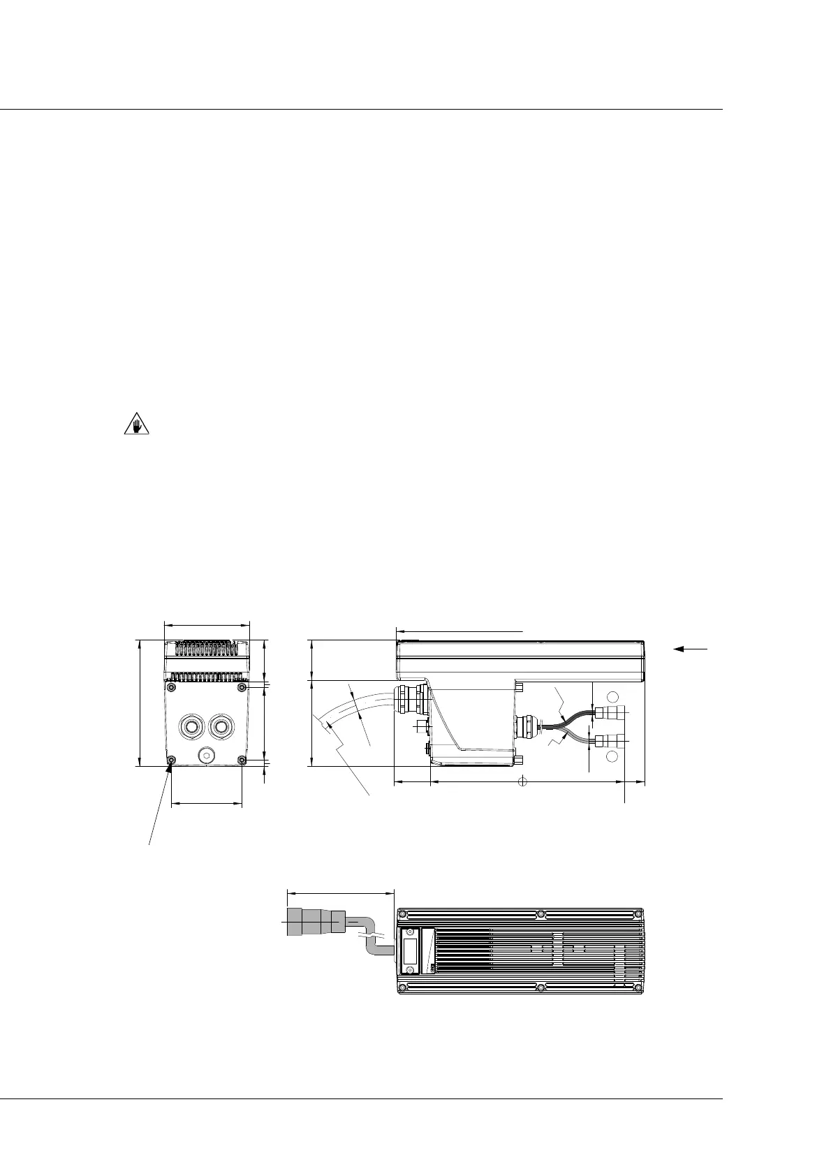
CPH 400 B fixing
To install the electronic drive on the user machine, use the 4 supports/spacers (with screws) on the
corners of the flange housing the outlet cable connections (ref. D on page 25). Use 4 galvanised
M4 screws, minimum strength class 8.8.
Place the drive onto the support surface to which it has to be fixed, in line with the holes
provided;
Fix the drive using n° 4 galvanised M4 screws of suitable length;
Tighten the 4 screws.
In order to ensure the necessary electrical conductivity, use galvanised screws only.
Tightening torque of the screws
M4 screws = 5 Nm
CPH 400 B overall dimensions
More useful information on fixing can be found in the appendix A “Technical characteristics”.
13
14
Rminimo
p. fissa 27,6
p. mob. 55,2
Rminimo
p. fissa 31,2
p. mob. 58,5
1
1
O
R
1
1
0
m
i
n
i
m
o
O7,8
O9,2
67
==
(120)
81
6
69
5,7
39,3
82 38
0 11688122
120
300
C
view from C
M4 x ↧ 4 n°4 holes in the supports/spacers