5 Installation and commissioning
32
HSD S.p.A. © - h0104k02a.fm091115
5.4 Mechanical connections
The load-bearing structure, on which the product is to be mounted, must be sufficiently rigid to
support the weight and type of machining to be carried out.
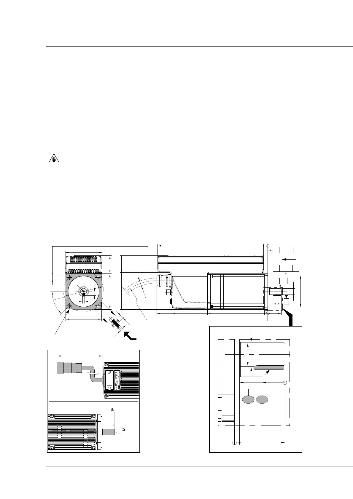
SM 141 D fixing
To fix the servo-motor onto the user machine, use the 4 support holes placed on the support flange
(ref. D, page 24). Use 4 M6 screws, minimum strength class 8.8.
In order to ensure the necessary electrical conductivity, use galvanised screws only.
Tightening torque of the screws
M6 screws = 15 Nm
SM 141 D overall dimensions
^0,02
A
a
O0,04
A
n 0,04 A
C
C
Se
z
i
on
e
C
-C
M5 x 8
010246
0
3 30
18
135214
14O h6
3882,5
70O h7
7,5
7,5
6
,
5
81
80
80 40,5
4
5
°
O
9
0
5
9
248
R
1
1
0
m
i
n
im
o
1
1
O
B
view from B
Ø 6,5, 4 through bores with 90°
section C-C
Key 5x5x18
UNI 6604 A
DIN 6885 A