5 Installation and commissioning
48
HSD S.p.A. © - h0104k02a.fm091115
Two devices on the same field-bus line cannot have the same address.
Only change the configuration of the Dipswitches when the board is not powered up
.
All 32 combinations between 0 and 31 are allowed.
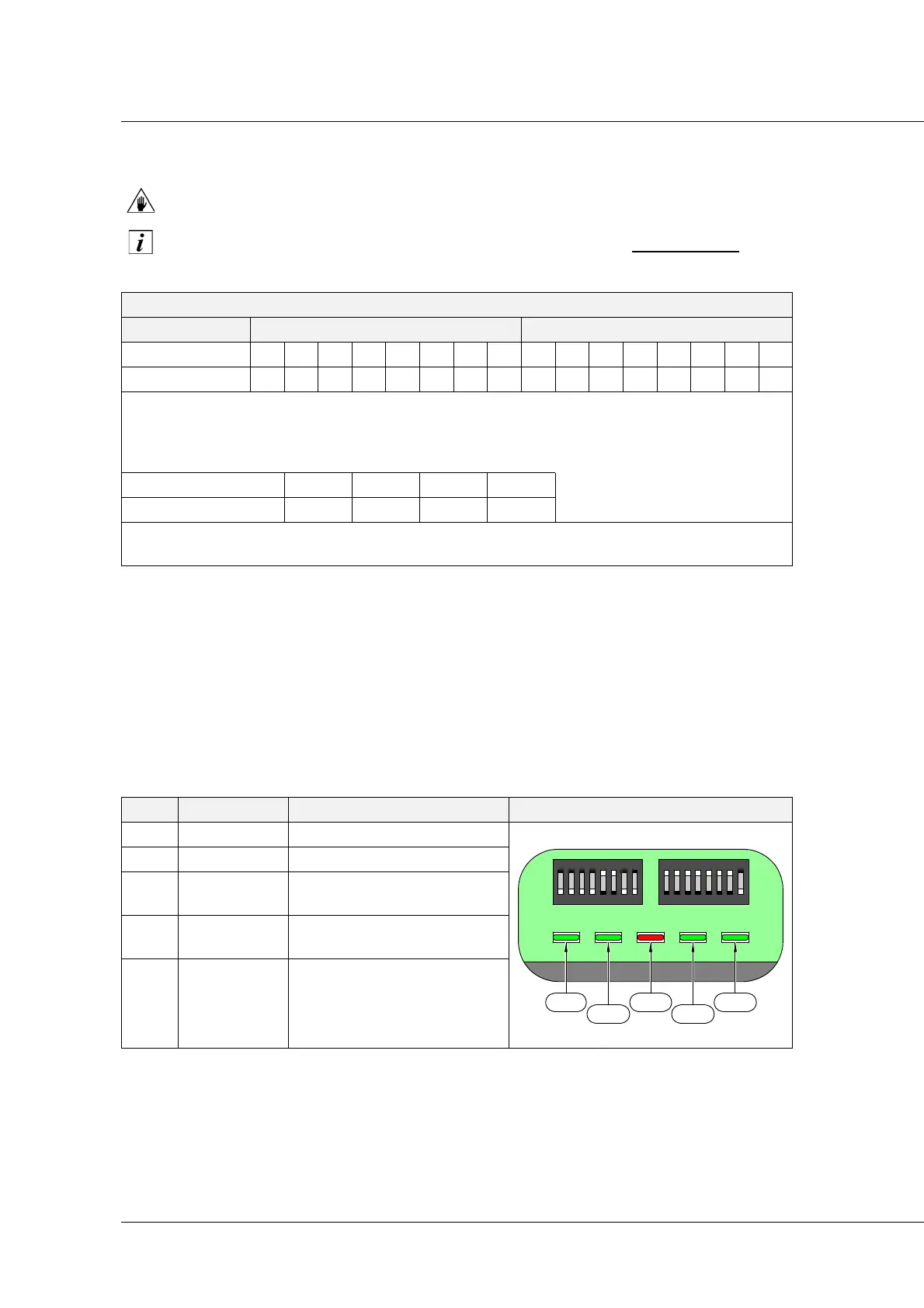
5.9 Diagnostics
Here below is stated the led diagnostics (ref. A, page 46).
The drive displays a lot of messages through CNC. For further information on CNC diagnostics,
refer to the User Manual “Diagnostics and Parameterisation” (for Smart Motors and Drives)
distributed by HSD S.p.A..
SERVICE MODE
DSW DSW1 DSW2
Switch 1234567812345678
Switch status On On Off Off Off Off On On Off Off Off Off Off Off FOn
F = Off at start-up (necessarily); after this the brake is controlled by dipswitch:
Off = brake unlocked / On = brake locked (activated with board powered)*.
The input from connectors 1 to 4 of page 38 is take to the diagnostics LEDs as indicated in the
table below.
*
When the park brake is present.
Input (# connector) 1234
Output LED1 LED2 LED4 LED5
NOTE 1: the+24 V DC power supply must be sent through connector 5.
NOTE 2: with the Service mode, the motor doesn't communicate via Fieldbus.
LED ACTIVITY MEANING LED LAYOUT
LED1 OFF Always OFF
LED2 ON Always ON
LED3
LOGICAL red
led
If it is ON, the logical power is
present in the drive.
LED4
READY
green led
When it is enabled, the drive
is working on Fieldbus.
LED5 OFF Always OFF
LED 1
LED 2
LED 3
LED 4
LED 5