5 Installation and commissioning
38
HSD S.p.A. © - h0104k02a.fm091115
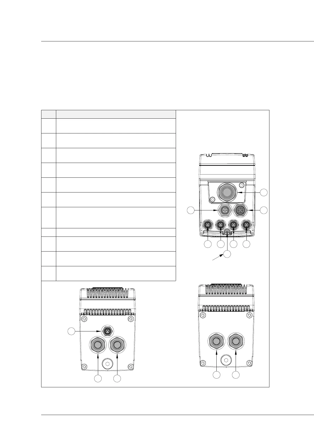
Electric connectors
The device is fitted with 7 connectors on the connections panel (one power connector, ref. 7, 2
field bus and logic power connectors, ref. 5-IN and 6-OUT, and 4 digital input connectors, ref. 1, 2,
3, 4). The CPH400 has other connectors, one for motor power (ref. 9), one for the encoder (ref. 10)
and one for piloting the brake in the version with same (ref. 11).
Ref. Description user side view
1
Digital input or Positive Overrun;
M8 - 3-pole female connector
2
Digital input or Negative Overrun;
M8 - 3-pole female connector
3
Digital input or thickness tracer input;
M8 - 3-pole female connector
4
Digital input or reset input;
M8 - 3-pole female connector
5
Field bus input and logic power;
M12 - 5-pole male connector
6
Field bus output and logic power;
M12 - 5-pole female connector
7
Power cable input;
7/8” connector - 5-pole male (350W version)
M23 connector - 6-pole male (450W version)*.
*
Only for SM141D GREEN.
8 Functional earthing without interference.
9
Motor power output;
M16 connector - 8-pole female.
10
Encoder input;
M16 connector - 10-pole female.
11
24 V dc brake pilot digital output;
M8 connector - 3-pole female.
M3 x 3 Galvanised +
Schnorr galvanised washer