Figures
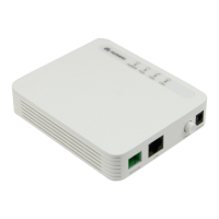
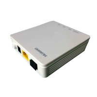
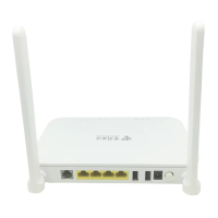
Figure 2-1 Appearance of the HG8240................................................................................................................2-3
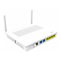
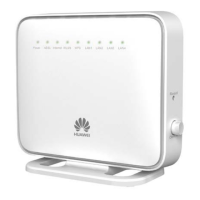
Figure 2-2 Appearance of the HG8245................................................................................................................2-3
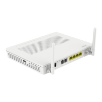
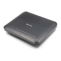
Figure 2-3 Appearance of the HG8247................................................................................................................2-4
Figure 2-4 Ports on the rear panel of the HG8240...............................................................................................2-4
Figure 2-5 Ports on the side panel of the HG8240...............................................................................................2-5
Figure 2-6 Ports on the rear panel of the HG8245...............................................................................................2-6
Figure 2-7 Ports on the side panel of the HG8245...............................................................................................2-7
Figure 2-8 Ports on the rear panel of the HG8247...............................................................................................2-8
Figure 2-9 Ports on the side panel of the HG8247...............................................................................................2-9
Figure 2-10 LEDs on the HG8240.....................................................................................................................2-10
Figure 2-11 LEDs on the HG8245.....................................................................................................................2-11
Figure 2-12 LEDs on the HG8247.....................................................................................................................2-11
Figure 2-13 Network topology of the HG8240..................................................................................................2-14
Figure 2-14 Network topology of the HG8245..................................................................................................2-14
Figure 2-15 Network topology of the HG8247..................................................................................................2-15
Figure 3-1 Configuring the GPON FTTH Internet service................................................................................3-11
Figure 3-2 Configuring the GPON FTTH Internet service................................................................................3-22
Figure 3-3 Configuring the GPON FTTH voice service (H.248 protocol)........................................................3-36
Figure 3-4 Configuring the GPON FTTH voice service (SIP protocol)............................................................3-52
Figure 3-5 Configuring the GPON FTTH multicast service..............................................................................3-68
Figure 3-6 Configuring the GPON FTTH multicast service..............................................................................3-83
Figure 3-7 Flow chart.......................................................................................................................................3-174
Figure 3-8 Login interface................................................................................................................................3-184
Figure 3-9 Flowchart for commissioning interoperation between the U2560 and the ONT through the Web page
...........................................................................................................................................................................3-203
Figure 3-10 Exporting the XML configuration file..........................................................................................3-233
Figure 3-11 Importing the XML configuration file..........................................................................................3-234
Figure 3-12 Exporting the XML configuration file..........................................................................................3-235
Figure 3-13 Importing the XML configuration file..........................................................................................3-237
Figure 3-14 Exporting the XML configuration files........................................................................................3-238
Figure 3-15 Importing the XML configuration files........................................................................................3-239
Figure 4-1 General troubleshooting flowchart.....................................................................................................4-3
Figure 4-2 Appearance of the PPM-350B optical power meter...........................................................................4-7
Figure 4-3 Measurement points of the optical power in the GPON network.......................................................4-8
EchoLife HG8240/HG8245/HG8247 GPON Terminal
Service Manual Figures
Issue 04 (2011-01-12) Huawei Proprietary and Confidential
Copyright © Huawei Technologies Co., Ltd.
xiii
 Loading...