Prerequisites
Connectors for an alarm cable are prepared.
Context
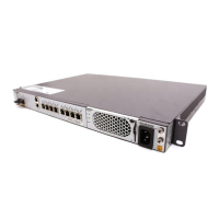
Figure 4-36 shows the exterior of an RHUB alarm cable. 4.4.2 RHUB Cable List shows the
installation position on both ends of the RHUB cable.
Figure 4-36 RHUB alarm cable
Procedure
Step 1 Connect the RJ45 connector on one end of the alarm cable to the EXT_ALM port on the RHUB.
Step 2 Connect the other end of the alarm cable to the alarm cable port on the device to be monitored.
----End
4.4.9 Installing an RHUB Power Cable
The RHUB power cable provides 110 V AC/220 V AC power supply for the RHUB.
Procedure
Step 1 Route the power cable by referring to 4.4.1 Requirements for Cable Layout.
Step 2 Connect the power connector on the X1 end to the AC power input port on the RHUB panel, as
shown in Figure 4-37.
Step 3 Connect the power connector on the X2 end to the external power supply port, as shown in
Figure 4-37.
LampSite
Installation Guide 4 Installing an RHUB
Issue 02 (2014-05-27) Huawei Proprietary and Confidential
Copyright © Huawei Technologies Co., Ltd.
39
 Loading...

