ip address 20.20.20.1 255.255.255.0
arp broadcast enable
#
return
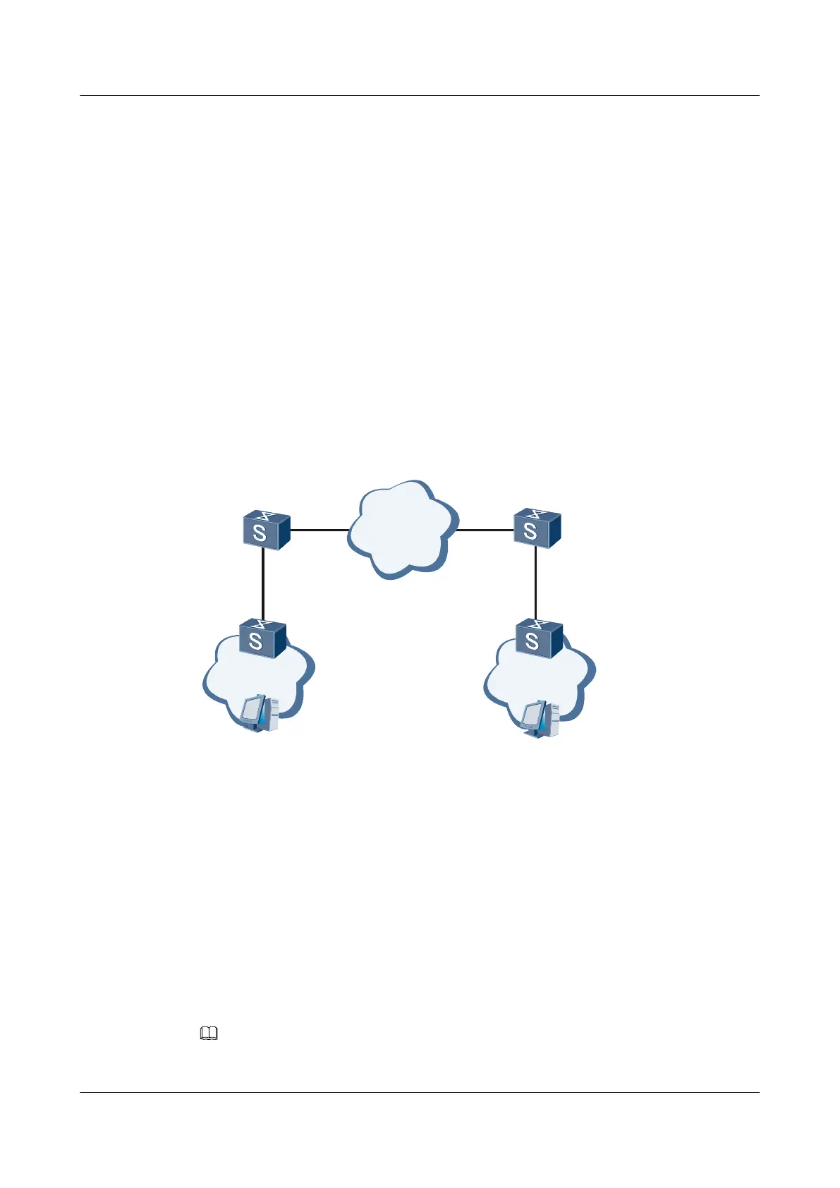
3.12.8 Example for Configuring Communication Across a Layer 3
Network Through the Sub-interface
Networking Requirements
As shown in Figure 3-17, Switch A and Switch B are connected to Layer 2 networks that VLAN
10 belongs to. Switch A communicates with Switch B through a Layer 3 network where OSPF
is enabled.
It is required that the computers of the two Layer 2 networks be isolated at Layer 2 and interwork
at Layer 3.
Figure 3-17 Networking diagram for configuring communication across a Layer 3 network
through the sub-interface
GE1/0/1.1
GE1/0/1GE1/0/2
GE1/0/2.1
VLAN 10
VLAN 10
OSPF
SwitchA SwitchB
Configuration Roadmap
The configuration roadmap is as follows:
1. Add interfaces to VLANs.
2. Assign IP addresses to VLANIF interfaces.
3. Set the encapsulation type of the sub-interface.
4. Configure the VLAN allowed by the sub-interface.
5. Assign IP addresses to sub-interfaces.
6. Configure basic OSPF functions.
NOTE
The VLAN allowed by the sub-interface cannot be created globally.
Quidway S7700 Smart Routing Switch
Configuration Guide - Ethernet 3 VLAN Configuration
Issue 01 (2011-07-15) Huawei Proprietary and Confidential
Copyright © Huawei Technologies Co., Ltd.
137

 Loading...