vlan batch 10
#
interface Vlanif 10
ip address 100.1.1.2 255.255.255.0
#
interface GigabitEthernet1/0/0
port link-type trunk
port trunk allow-pass vlan 10
#
return
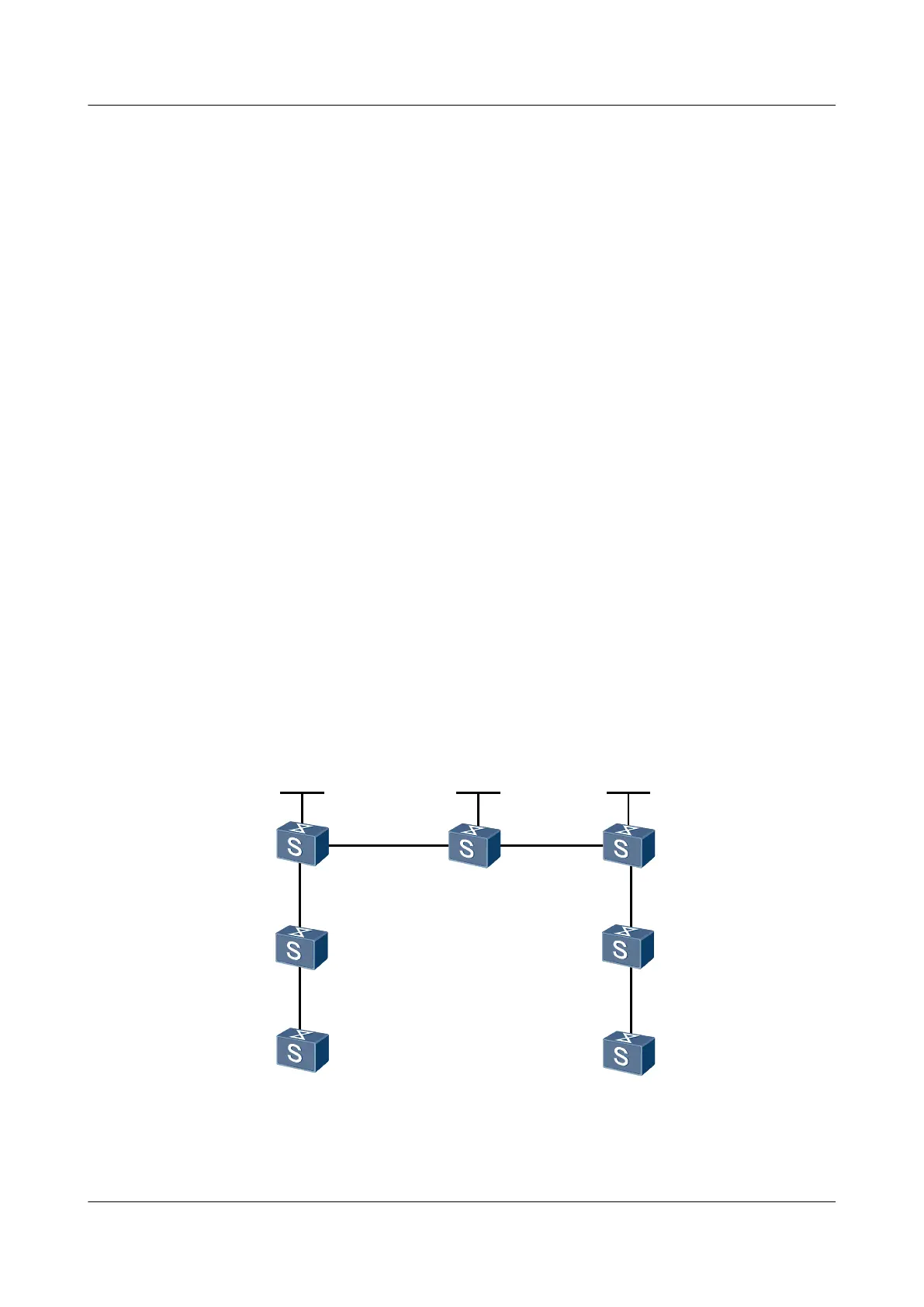
5.12.7 Example for Connecting QinQ Sub-interfaces to a VLL
Network
Networking Requirements
As shown in Figure 5-7, CE1 and CE2 are connected to PE1 and PE2 respectively through
VLANs.
A Martini VLL is set up between CE1 and CE2.
Switch1 is connected to CE1 and PE1.
Switch2 is connected to CE2 and PE2.
It is required that you configure selective QinQ on the interfaces connected to CEs so that the
switches add the VLAN tags specified by the carrier to the packets sent from CEs.
When a switch is connected to multiple CEs, the switch can add different VLAN tags to the
packets from different CEs, that is, packets with different VLAN tags. This saves VLAN IDs
on the public network.
Figure 5-7 Networking diagram for configuring a Martini VLL
CE1
CE2
PE1
PE2
P
Loopback1
1.1.1.9/32
Loopback1
2.2.2.9/32
Loopback1
3.3.3.9/32
GE2/0/0
GE1/0/0
GE2/0/0
GE1/0/0
GE1/0/0
GE2/0/0
GE1/0/0
GE1/0/0
GE2/0/0
GE1/0/0
GE2/0/0
GE1/0/0
Switch2
Switch1
Switch
Interface VLANIF interface IP address
PE1 GigabitEthernet1/0/0 GigabitEthernet1/0/0.1 -
Quidway S7700 Smart Routing Switch
Configuration Guide - Ethernet 5 QinQ Configuration
Issue 01 (2011-07-15) Huawei Proprietary and Confidential
Copyright © Huawei Technologies Co., Ltd.
238

 Loading...