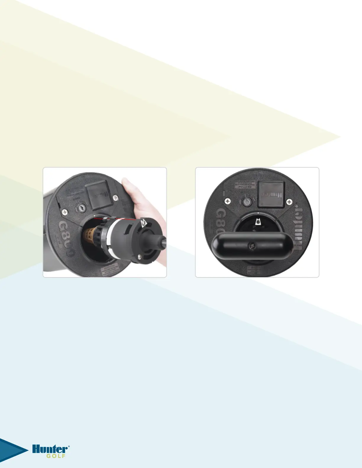
Next, insert the assembled tool, white lower snap ring and inlet valve into the rotor’s body cavity. To do so, it is
necessarytoalignthepointerarrowontheG800ValveToolwiththealignmentdotontherotor’sange.The
alignmentdotiscenteredontheangecompartmentlidadjacentto(nextto)thebodycavityopening(g107).
Asecondalignmentdotislocatedbelowthelidincasetheangecompartmentlidhasbeenremoved.Alignthe
pointer arrow on the tool with the alignment dot and lower the assembled tool, white lower snap ring and inlet valve
into the rotor’s body.
As the G800 Valve Tool is lowered into the rotor’s body, recessed areas on the black plastic part on the tool will
engage vertical rails inside the body wall (g 108). The tool must engage these rails or the inlet valve’s communication
port will not align with the communication port in the body cavity below. Continue pressing the assembled tool,
white lower snap ring and inlet valve downward into the rotor’s body. Once the tool reaches the bottom, continue
pressing rming to securely seat the inlet valve and snap ring.
A distinct “click” sound should be heard as the snap ring is released and engages the snap ring groove in the rotor’s
body cavity. After the inlet and white lower snap ring have been properly seated, press down on the tool then rotate
counter-clockwise to disengage the tool’s metal hooks from the inlet valve. Next, raise the G800 Valve Tool out of
the body. Finally, take whatever time is necessary to visually conrm that every part of the white lower snap ring is
securely seated into the snap ring groove.
FIG 107 FIG 108
35