Inlet valve installation option 2 – The alternative method to installing the G800 inlet valve is to use the 16”
Needle-Nose Pliers Tool. First look at the top of the inlet valve and notice the raised wall or rib that protrudes
upward from the center. During installation, the 16” Needle-Nose Pliers Tool is used to grab this protruding rib on
the inlet valve. Next, look at the side of the inlet valve and notice the communication port. During installation, this
communication port must engage the communication port at the bottom of the rotor’s body cavity. Now notice that
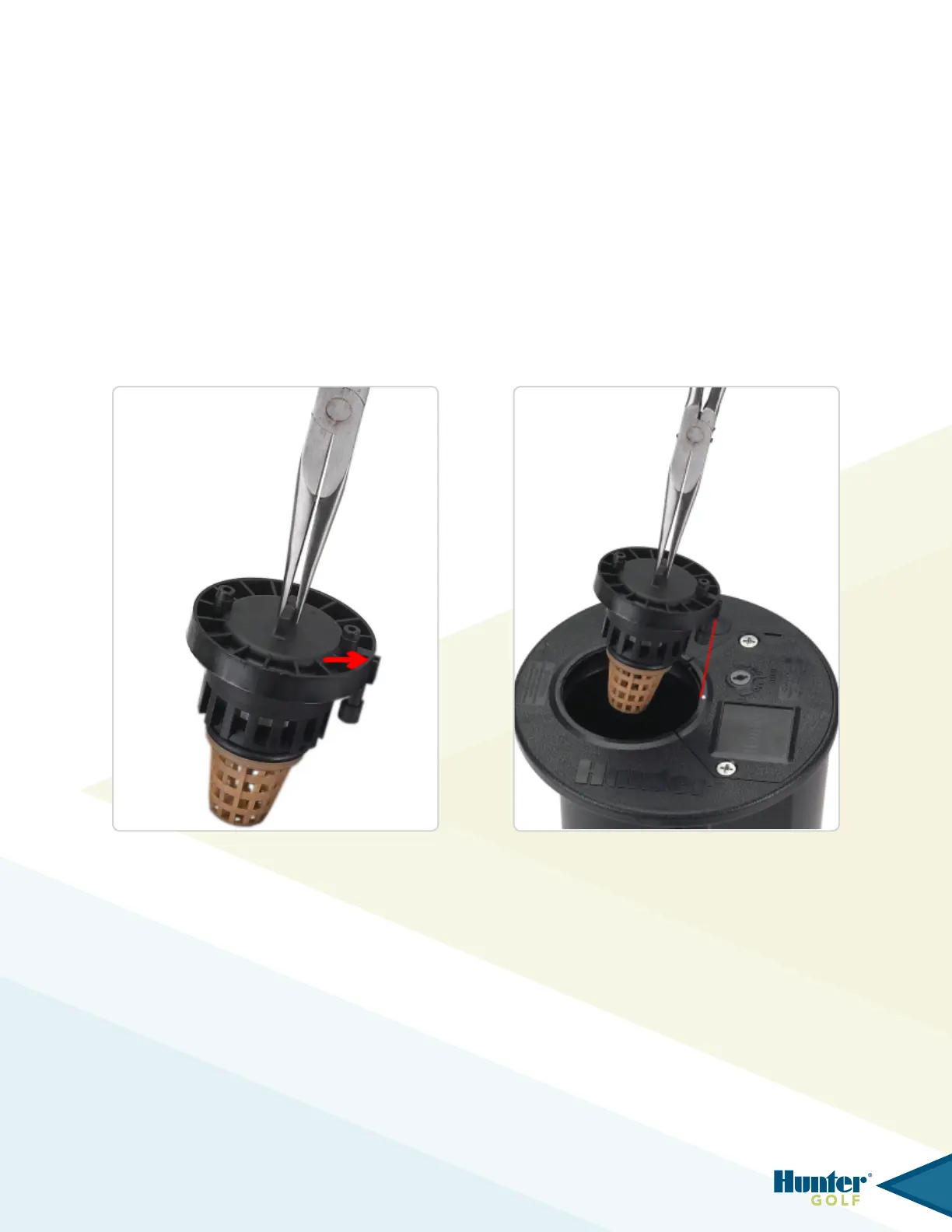
directly above the communication port there is a slot feature on the valve’s outside ring (g 109). During installation,
this slot feature must engage the vertical rail of plastic located on the rotor body’s inside wall. The vertical rail is
located directly above the communication port at the base of the rotor’s body cavity.
Grab the protruding rib on the inlet valve rmly with the 16” Needle-Nose Pliers Tool. Next, insert the inlet valve
into the rotor’s body cavity. It is necessary to align the valve’s communication port and/or the slot feature with the
alignmentdotontherotor’sange(g110).Thealignmentdotiscenteredontheangecompartmentlidadjacent
to(nextto)thebodycavityopening.Asecondalignmentdotislocatedbelowthelidincasetheangecompartment
lid has been removed.
FIG 109 FIG 110
36