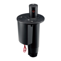
With the valve’s communication port and/or the slot feature aligned to the dot on top of the rotor, carefully lower the
inlet valve into the rotor’s body. If the inlet valve is properly engaged with the vertical rail in the body, it will not be
possible to rotate the inlet valve. If the inlet valve can be rotated in either direction, pull the inlet out and start again.
With the inlet valve engaging the body’s vertical rail, continue lowering the valve into the rotor’s body. It is important
to keep the inlet valve vertical in order to allow the valve’s rock screen to enter the inlet of the body. Once the inlet
valve reaches the bottom, continue pressing rming to securely seat the inlet valve.
Next, use the 16” Needle-Nose Pliers Tool to install the white lower snap ring. To do so, use the tool to grab the
outer side of the two raised areas near the ends of the white lower snap-ring (g 111). The snap ring must be installed
with these two raised & protruding areas on the snap ring ends facing upward. Next, squeeze the two raised areas
together with the tips of the 16” Needle-Nose Pliers Tool. This action will collapse the white lower snap-ring. While
holding the collapsed white lower snap-ring with the tool, lower the white lower snap ring into the rotor’s body (g
112). Next, engage and release the snap ring into the snap ring groove located at the base of the body cavity wall.
Finally, take whatever time is necessary to visually conrm that every part of the white lower snap ring is securely
seated into the snap ring groove (g 113).
Caution! If snap-ring in not fully seated in the snap-ring groove, the valve may be expelled from the rotor
when the piping is re-pressurized. Serious bodily injury can occur. Keep head and body parts away from the
rotor when piping is being re-pressurized.
FIG 111 FIG 112 FIG 113
37
 Loading...
