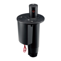
Withtheangecompartmentlidremovedandpriortodisassembly,taketimetonotetheorientationofthevarious
componentswithintheangecompartment(g128).Thiswillbevaluablelaterforreferenceduringnalassembly.In
particular notice:
• Howthesolenoidwiresfoldoverthetopandtotheatsideofthesolenoid
• How,intheAutoposition,theatonthesideofthesolenoidfacestotheoutside
• Howthepilotvalve’sttingsandconnectedtubingpointinaspecicdirection
• Howthepressureregulatoristuckedintopositionwithinthecompartment
Selector Cap Removal
The Selector Cap turns the Solenoid when the user changes the ON-AUTO-OFF settings. Under normal operating
conditions, the Selector Cap should not need replacement. The Selector Cap can become damaged if the incorrect
tool is used to make ON-AUTO-OFF selection adjustments. Prior to removing the Selector Cap, notice that the
Solenoid wires run over the top of the Solenoid and out of the Selector Cap on the side of the Solenoid that has the
atsurface.AlsonotethattheSolenoidwiresarepositionedside-by-sideandnottwisted.ToremovetheSelector
Cap, simply lift it up and away from the Solenoid (g 129).
FIG 128 FIG 129
42
 Loading...
