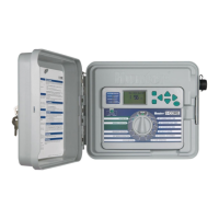
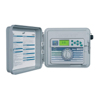
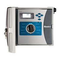
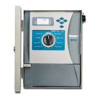
MOUNTING
THE CONTROLLER TO WALL
Wall
Mount
for Plastic and
Metal
Cabinet
All necessary
mounting
hardware
is
included with your controller and
should
be
suitable
for
most installations.
Tools required:
Long drill
bit
and extension Philips screwdriver
or
bit
(for use with long
extension) - magnetic recommended Wire strippers
NOTE: This controller must be installed
in
compliance
with local electrical codes.
Location Requirement:
A) A switch
or
circuit-breaker shall be included
in
building
installations;
B)
the
switch
or
breaker shall
be
in
close proximity
to
the controller and within easy reach
of
the operator; C)
the
switch
or
breaker shall
be
marked
as
the
disconnecting device
for
the controller;
D)
the
switch
or
circuit breaker used must comply with
IEC
60947-1 and
IEC 60947-3.
Select a location
for
your controller that can
be
easily accessible,
has
a flat wall surface, and
is
within close proximity
to
a 120VAC(1
OA)
or
230/240VAC(SA)
power
source.
In
outdoor
installations, avoid direct exposure
to
sprinkler spray. Shaded
or
partially shaded areas are preferable
to
prolonged
direct sunlight.
1.
Using
the
enclosed
mounting
template, mark the
mounting
hole
locations on the wall. It should
be
mounted
at
eye level
if
possible.
2.
Drill a W'
(6
mm) hole at each mark.
3.
Install screw anchors
into
holes
if
attaching the controller
to
drywall,
masonry,
or
plaster walls.
4.
Open
the controller and inner
door
. The inner
door
will swing
out
of
the
way
to
provide full access
to
the controller
mounting
holes.
5.
Holding
the
controller cabinet, line
up
the
holes
in
the
cabinet with
the
wall
anchors
or
pilot
holes.
6.
Drive a screw through each hole and secure snugly
but
do
not
over
tighten
.
7.
OPTIONAL: Locate
the
positioning hanger
in
the
upper
center
of
the
controller
(A)
. Install one screw
(B)
in
this hanger position and hang
the controller from
the
keyhole slot. Place a level on the
top
of
the
controller cabinet and level. Locate and drive a screw
in
each
of
the
remaining screw holes
(C),
and secure snuggly
but
do
not
over
tighten
the
screws.
0