CONNECTING THE POWER
AND
STATION MODULES
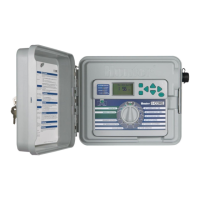
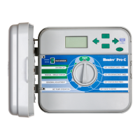
The I-Core controller
is
supplied with one factory installed
power
module
and one station module
for
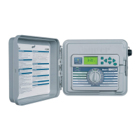
six stations. Additional station modules may be
added
in
six station increments
to
expand the controller's station capability.
The plastic cabinet
I-Core
can
be
expanded
to
a
size
of
30 stations, and the
metal cabinet and plastic pedestal
I-Core
can
expand
to
42 stations.
STATION MODULE
Power
Module
Slide
Lock
Station
Modules
Station
Module
Installation
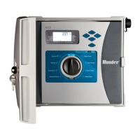
1.
Open the inner facepack
door
and locate the Slide Lock. Move the
Slide Lock bar
to
the POWER OFF position.
2.
The module needs
to
be inserted into the first open module slot
position from the left
or
next available position
in
the back
of
the
controller. Do not skip slots by leaving them empty.
3.
Insert the module with the
gold
tab on the
top
of
the module facing
up.
Slide the module straight
in
until it clicks into place.
4.
Slide the Slide Lock into the POWER ON position.
5.
Th
e controller will automatically identify any new modules that have
been added.
You
can
turn the dial
to
SET
STATION RUN TIMES
to
confirm the correct number
of
stations have been acknowledged.
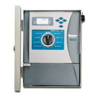
Power Module Installation
The I-Core
power
module supplies power
to
the facepack and accessory
terminals.
It typically does
not
need
to
be removed, however
can
be
replaced
for
servicing.
1.
To
install the Power Module, open the inner facepack door,
and locate the module lock bar. Move the
Sl
ide Lock bar
to
the
POWER OFF position.
2.
Insert the
power
module into the first slot position from the left, with
the
gold
tab on the
top
of
the module facing up. Slide the module
straight
in
until it clicks into place.
3.
Move the
Sl
i
de
Lock
to
the POWER
ON
position.
4.
The Power
Module
must be
in
place
in
order
for
the controller
to
operate and function.