DC Electric Systems
7.4
followed:
Turn off all power drawing breakers and isolate bat-
tery.
Remove negative (-) cable first, then the positive (+).
To install a battery, the following procedure should be
followed:
Attach the positive cable to the positive (+) terminal
on the battery.
Attach the negative cable to the negative (-) terminal
on the battery.
NOTE: Batteries should always be removed and installed by
trained, qualified persons to avoid potential damage.
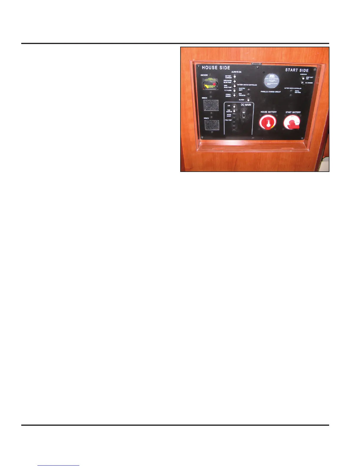
7.2.2 Battery Switch Panel
The Battery Switch Panel (BSP) is mounted within the
inboard face of the nav station seat (Fig. 7.4). The
battery banks are connected to the round battery selec-
tor switches on the panel with the respective labels of
“House Battery” and “Start Battery”.
The Start Battery selector switch is a two
position switch: “OFF” (12 o’clock) and
“ON” (3 o’clock). The House Battery selector switch is a
three position switch: “OFF” (12 o’clock), “ON’ (3 o’clock)
and “COMBINED” (5 o’clock).
Turning the selector switch to “ON” turns power on to
the respective circuits. Turning the selector switch to
the “OFF” position turns power off to the respective cir-
cuits. Turning the House Battery selector switch to the
“COMBINED” position allows both the House and Start
batteries to simultaneously source power. Consequently,
power for both engine starting and house components
can be sourced from a single battery or combined bat-
teries.
The “DC Main” switch circuit breaker on the BSP provides
power to the main DC Panel (see Fig. 7.9) for the house
components.
The BSP also houses the breakers for some of the main
components in your DC system. The breaker controls are
marked on the panel and they control systems or compo-
nents on your boat that require an energized connection
even through the main DC Panel may be de-energized.
1.
2.
1.
2.
Figure 7.4
7.2.3 Battery Charger
An optional battery charger (see Fig. 7.5) is available
to assist in maintaining charged batteries. It can be
accessed through the port aft settee lid in the main salon.
A 50 amp pop-out breaker exists on the Battery Switch
Panel labeled “Battery Charger” and protects the charg-
ing system from a power fault following the AC panel. A
15 amp toggle switch breaker labeled “Battery Charger”
exists for the battery charger on the AC panel which pro-
tects the battery charger from an AC system power fault
(see AC Electric System chapter in this manual).
To charge the batteries, complete the following:
Connect the shore power cable (Fig. 7.6) to line 1 on
the shore power inlet located in the transom garage
(see Fig. 7.7).
Turn on main AC panel breaker (see AC Electric
System chapter in this manual).
Turn on the battery charger breaker on the AC Panel
(see AC Electric System chapter in this manual).
NOTE: Consult the charger manufacturer’s OEM manual for
charger operation, care and maintenance.
7.2.4 Engine Alternator
While your batteries can charge dock side through the
battery charger or inverter (discussed later), they can
1.
2.
3.