DC Electric Systems
7.5
also charge when under power through the engine alter-
nator (see Fig. 7.19).
Figure 7.5
Figure 7.6
Figure 7.7
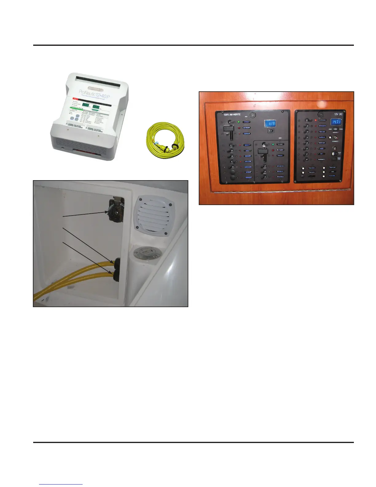
7.2.5 DC Panel
The DC panel (DCP) is located forward of the AC panel
on the hull panel of the nav station (Fig. 7.8). Please
refer to Fig. 7.0 and note the systems and components
controlled by the main DC Panel. Notice when the bat-
tery selector switch is on, the respective battery voltage is
shown in the upper right digital volt meter display. Also,
indicator lights are built into the breaker switches to alert
a selected system is powered.
7.2.6 Breakers, Switches and Fuses
All electrical systems aboard your boat are equipped with
over-current protection in the form of breakers or fuses
(Fig. 7.1 amperage table). All systems and components
on the Battery Switch Panel and DC Panel are protected
with breakers. Specific systems or components have
been equipped with breaker switches for convenience in
manually interaction.
Figure 7.8
7.2.7 Inverter
An optional inverter is available to convert DC power to
AC (see the AC Electric System chapter in this manual
for further details). The assembly consists of the inverter
(Fig. 7.10) and a remote panel (Fig. 7.11). The inverter
can be accessed through the port aft settee lid in the
main salon. The remote panel is located on the hull panel
of the nav station near the optional VHF radio and chart
table light.
A secondary feature of the inverter is its battery charging
capability. The batteries will charge if shore power or the
optional generator is connected and the main AC Panel
is energized.
7.2.7.1 Inverter Basic Operation
Choose the source battery(ies) and turn switch(es) to
the “On” (3 o’clock) position (or “COMBINED” on the
House Battery selector switch).
Turn on the inverter remote panel.
Turn on the main AC Panel breaker switch.
Turn on the appropriate appliance breaker on the AC
Panel (see the AC Electric System chapter in this
manual).
1.
2.
3.
4.