AC Electric Systems
8.1
In addition to the 12 Volt DC negative ground system,
your boat is equipped with a 120V 60 HZ AC system as
standard and a 230V 50 HZ as an option.
The purpose of this chapter is to provide information
necessary to understand and operate the AC electrical
system aboard your boat. This system comprises your
boat’s electrical components which are powered by 120V
(or 230V) AC power. We will organize this section into
the following topics:
AC Power System Overview
AC Power Supply Equipment and Components
AC System Components and Operation
The purpose of this chapter is not to educate on the
repair or the expansion of the electrical system. Nor is its
purpose to educate on the basics of electricity. Again, the
purpose is to provide you with the information to safely
operate and maintain the AC electrical system.
Electricity cannot be detected without the use of
specialized test equipment. Never think you know
whether a circuit is “live”. Always have qualified,
competent professionals inspect or make repairs to
your electrical systems.
Do not rely on the information in this manual as a
repair guide. As always, only competent electrical
service personnel should attempt to repair any elec-
trical equipment or to expand the electrical system.
Work performed by non-electrical service person-
nel may result in electrical shock or damage to the
boats systems or components.
8.1 AC Power System Overview
Please refer to 8.18 for the basic power supply equipment
and component layouts as reference for this section.
The sources of power for the three-wire grounded AC
systems aboard your boat are the following:
1.
2.
3.
Shore Power
Generator (Option)
Inverter (Option)
The overall control of that power is found in the AC Panel.
Individual remote panels for the optional generator and
inverter are also involved in the specific control of these
systems.
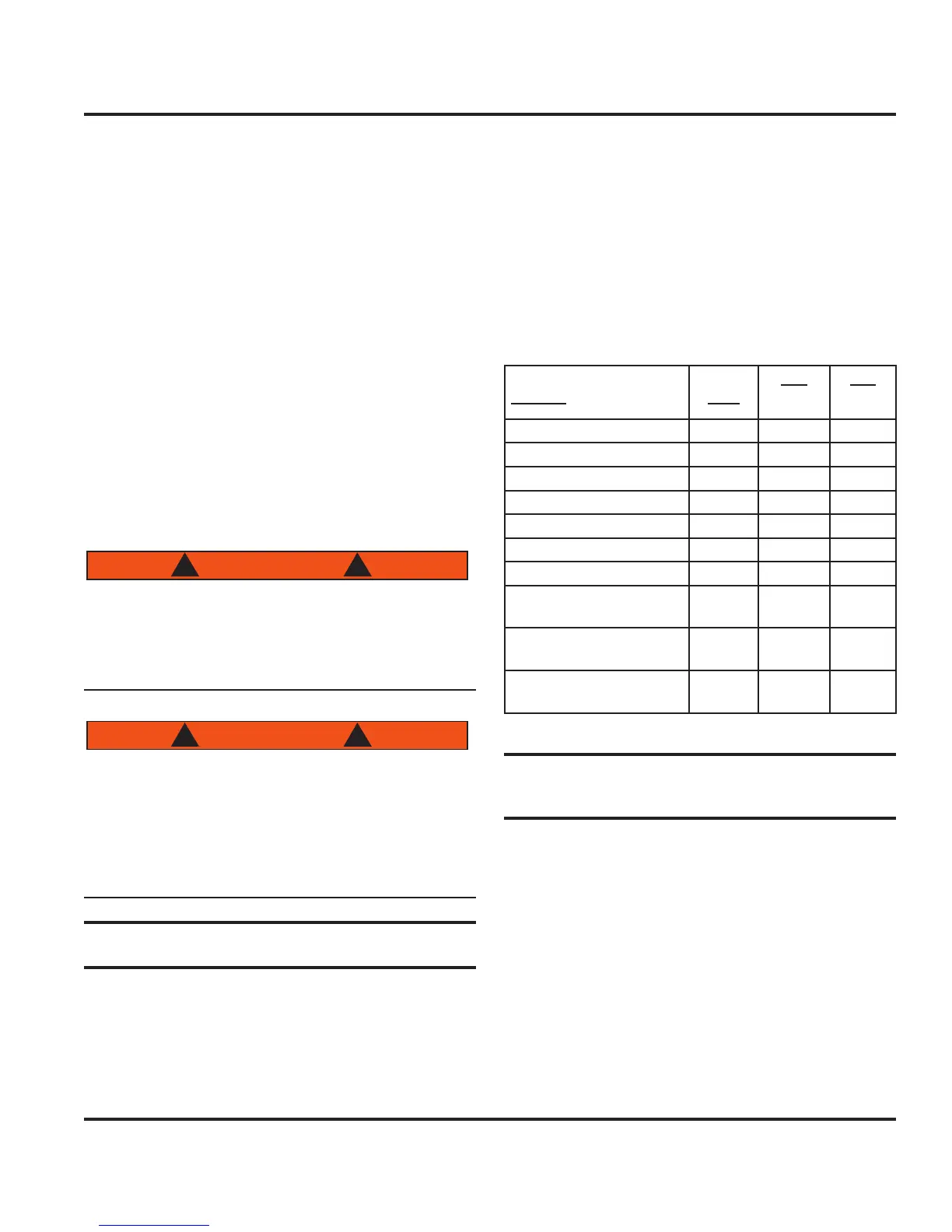
Please note Fig. 8.1 for the individual systems/compo-
nents controlled by the AC Panel and their corresponding
resettable breaker amperage.
System
Line
Brk
120V
(AMP)
Brk
230V
(AMP)
AC Main 1 & 2 30 DBL 15 DBL
Generator (Option) 1 50 DBL 30 DBL
Parallel 2 30 DBL 15 DBL
Outlets 1 20 10
Microwave (Option) 1 15 10
Battery Charger (Option) 1 15 10
Water Heater 1 15 10
Air Conditioner/Fwd
(Option)
2 25 15
Air Conditioner/Aft
(Option)
2 20 10
Air Conditioner Relay
(Option)
2 5 5
Figure 8.1
8.2 AC Power Supply Equipment and
Components
8.2.1 Shore Power
Power to energize your boat’s AC system can come from
a dock side shore power hookup and is the standard
method. The connection is located in the starboard side
transom garage. Figure 8.2 shows the inlet configura-
tion of three hookups: line 1, 2 and TV. Line 1 inlet is
the standard hookup for the boat’s AC system. Line 2 is
installed when the boat is equipped with the air condi-
tioning option. The TV inlet is installed when the boat is
equipped with the TV option.
8.2.1.1 Shore Power Inlet Breaker(s)
1.
2.
3.