AC Electric Systems
8.4
Figure 8.4
increase the life of the product. Similarly, in case of
salt water immersion, rinse plug end and/or connector
end thoroughly in fresh water, shake or blow out excess
water and allow to dry. Spray with moisture repellent
before re-use. Perform maintenance only after the cable
is unplugged from its power source. A soiled cable can
be cleaned with a grease cutting household detergent.
A periodic application of vinyl protector to both ends will
help to maintain cables original appearance.
DO NOT allow the dock side power cord to come
in contact with the water. Never operate any power
tool or other electrical equipment while you or the
devices are in contact with the water, as this may
cause electrocution resulting in shock or death.
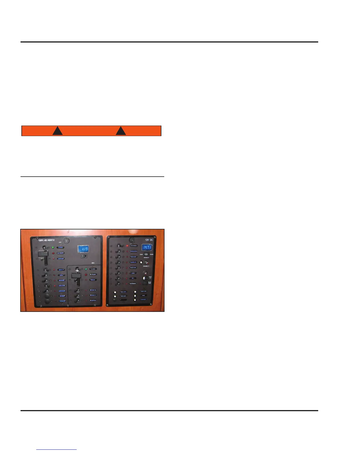
8.2.3 Main AC Panel
Once AC power is sourced, power is routed to the AC
Panel main breakers. The AC Panel is the left panel of
the double panels located at the nav station (Fig. 8.6).
Figure 8.6
8.2.3.1 Panel Lights
The power for the panel backlights for both the AC Panel
and DC Panel are provided by the DC system. Control
of the backlights is through a two-position rocker switch
labeled “Panel Lts” located on the DC Panel (see DC
Electric Systems chapter of this manual). This switch is
located middle right side of the DC Panel.
8.2.3.2 Volt Meter Line Selector Switch
Immediately below the digital volt meter, located at the
top-right corner of the panel, is a two-position rocker
switch for selecting the line for voltage display. One
side of the switch is labeled “1” and other is labeled “2”.
Position the switch to the desired line for a power level
display. The voltmeter will display the voltage of the lines
regardless if the AC panel is energized or not.
8.2.3.3 Breakers, Switches and Fuses
All electrical systems aboard your boat are equipped
with over-current protection in the form of breakers or
fuses. All systems and components on the AC Panel are
protected with toggle breaker switches for convenience
in manually interaction with those systems. A green LED
is associated with each switch breaker and will illuminate
when the breaker is in the “On” position.
8.2.3.4 Main AC Panel Breakers
Each line on the main AC Panel has a 30 amp toggle
double-breaker switch labeled “AC Main”. Once these
breakers are switched on, the corresponding AC Panel
component breaker(s) are energized.
8.2.4 Battery Power (DC System)
The AC system and battery powered DC system will
interact at times. These interactions will effect the level
of charge in the batteries. If the battery banks aboard
your boat loose charge (as power is used to energize the
DC system or inverted for the AC system), they can be
recharged through either the shore power connection, the
engine alternator or the optional generator.
Charging the batteries through shore power or the gener-
ator is accomplished through either the battery charger or
the inverter. Charging the batteries through the engine
alternator is by direct connection. The relevant following
sections will clarify the battery charging process.
8.2.5 Generator
An alternative source of power for the AC system is the
optional generator (Fig. 8.7). The generator system
includes the generator, plumbing (water and fuel), wiring
and a remote panel.
The generator will be located in the port aft storage
region and accessed through the cockpit’s port gull-wing
seat lid. The remote panel is located on the forward hull
panel of the nav station (Fig. 8.8)..