Water Systems
9.3
the head and galley, your boat features an optional cock-
pit shower/deck-washdown unit located in the lower star
-
board cockpit near the swim platform (Fig. 9.6).
NOTE: Operate the fresh water pump only when there is water
in the tank. Running the pump dry will damage the diaphragm.
NOTE: If the pump runs from time to time even though no water
is being used, a water leak most likely exists.. Check all lines for
leaks and repair immediately.
NOTE: Whenever servicing the fresh water pump, shut off the
water pump breaker at the DC panel.
Figure 9.5
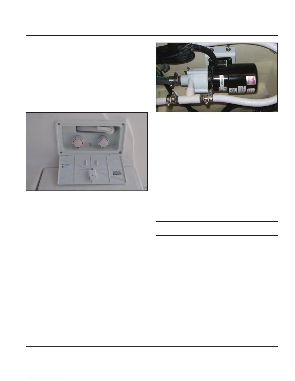
9.2.2 Air Conditioning Seawater Pump
The optional air conditioning units will require a water
pump to supply raw water to cool both compressors.
The pump (Fig. 9.6) is located in the main salon with
access through the main bilge floor panel.
Refer to Figure 9.15 for the full air conditioning water
supply layout.
The pump’s electrical circuitry incorporates a pump relay
panel which includes a toggle switch breaker on the AC
panel. When using the air conditioners, ensure the Air
Conditioner Relay switch breaker is switched “ON” (refer
to the AC Electric System chapter in this manual).
9.2.2.1 To Operate the Air Conditioner
Refer to the AC Electric System chapter in this manual for
a discussion on the electrical controls of this system.
NOTE: Consult the pump manufacturer’s OEM manual for fur-
ther details regarding operation, care and maintenance.
Figure 9.6
9.2.3 Generator Seawater Pump
The optional generator requires a water pump to supply
raw water to cool the compressor motor. This pump is
not a separately installed component but is part of the
generator assembly. Refer to the generator manufactur-
er’s OEM manual for information on pump operations.
9.2.4 Engine Seawater Pump
The engine requires a water pump to supply raw water to
cool the motor. This pump is not a separately installed
component but is part of the engine assembly. Refer to
the engine manufacturer’s OEM manual for information
on pump operations.
9.3 Pickups, Valves and Strainers
Your boat uses water pickups, valves and strainers to
supply water to the boat’s various systems.
9.3.1 Pick-ups
Pick-ups, or thru hulls, are placed in various locations in
the hull of your boat (refer to the Underwater Gear chap-
ter in this manual for details on thru-hull locations). The
pickups will incorporate a “Y” or ball type intake valve
(also referred to as a seacock) which controls the flow of
raw sea water to the specific component or system asso
-
ciated with the pick-up.
Figure 9.8 shows the intake, ball valve and strainer
associated with the optional air conditioning system. To
close the ball valve, rotate the handle to the straight up
position. To open the valve to seawater, rotate the valve