Waste and Sanitation Systems
10.2
Basically, all pumps are in some way associated with the
waste/sanitation system, but this section will only focus
on pumps that are directly associated with the process of
pumping waste overboard. The supply function of these
pumps are discussed in other sections.
Please refer to Figure 10.17 for the bilge/sump pump and
drain layouts as reference to the subsequent discussions.
Please reference the DC Electric System chapter of this
manual for details regarding control and circuit protection
of the waste related pumps.
10.2.1 Bilge Pumps
The safety of those on board your boat is a primary
objective. Therefore, we strongly encourage you review
all information contained in this manual, as well as the
manufacturer’s OEM manuals concerning all systems on
your boat. Specifically, the bilge pump system will be one
that is crucial to fully understand. These pumps have the
critical function of removing water from the bilges of your
boat. They must be kept clean and functional to ensure
they complete their task.
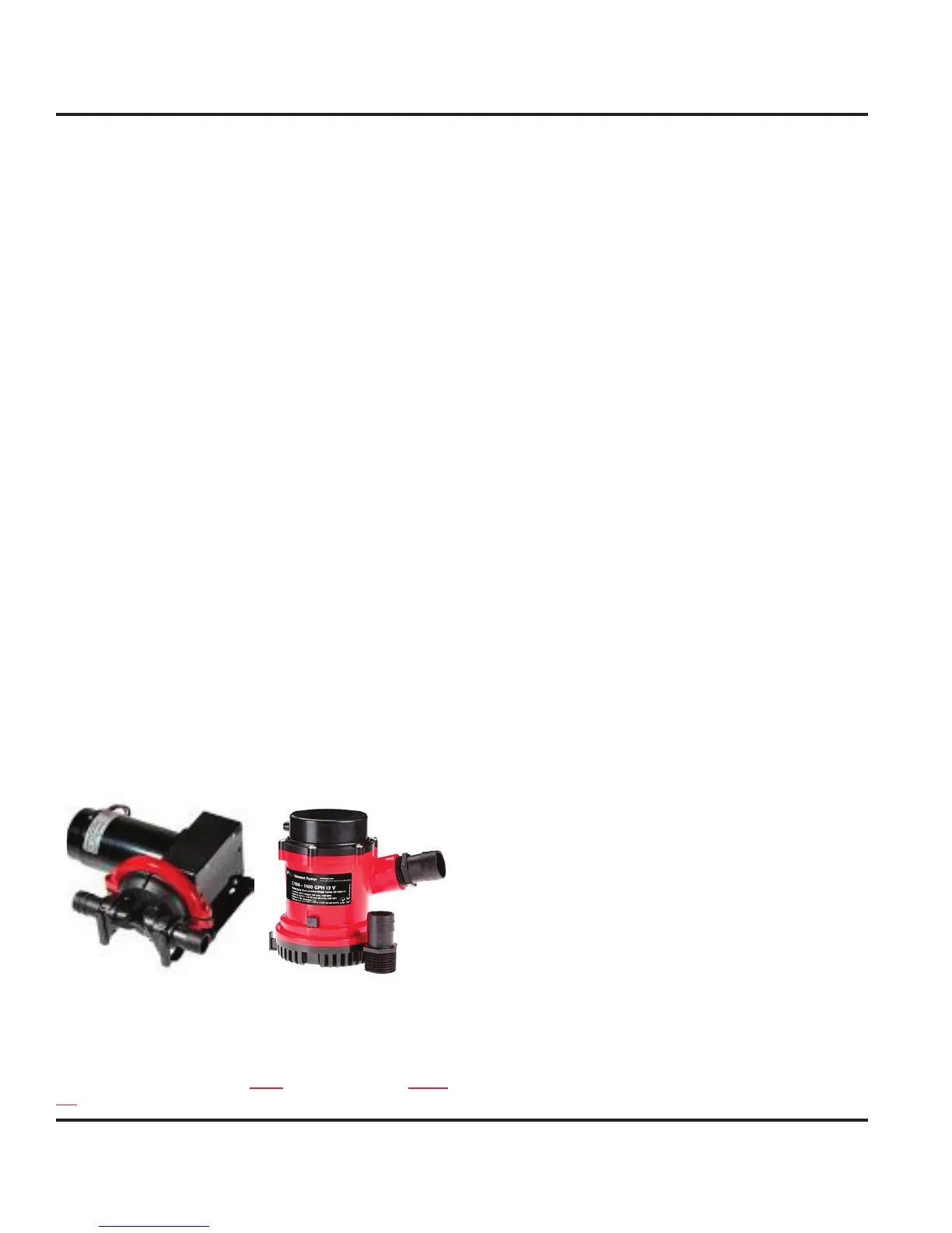
Your boat is equipped with 2 bilge pumps. The forward
bilge pump (Fig. 10.2) is installed in the anchor chain
compartment and accessed through the forward bunk
port drop-in. It has a pumping capacity of 4.2 gallons per
minute and functions to remove water from the anchor
chain locker generally due to anchoring. The main
bilge pump (Fig. 10.3) is installed in the main salon and
accessed through the main bilge floor panel. It has a
pumping capacity of 26.7 gallons per minute and is the
first responder in the event of water collection.
Figure 10.2 Figure 10.3
10.2.1.1 Main Bilge Pump Operations
NOTE: Power to the DC panel is not required in order to manu-
ally operate your bilge pumps.
To manually operate the bilge pumps, one can do either
of the following:
Flip and hold the toggle switch on the DC panel to the
right until the pump out is complete. The toggle will
spring back upon release.
For extreme circumstances, locate the float switch
near the pump and manually rotate the float handle
to simulate the float switch being under water. This
will energize the pump. Hold until the pump out is
complete.
10.2.1.2 Maintenance on Bilge Pumps
No maintenance is required beyond ensuring that the
float switches are operational and pump intakes are
debris free.
10.2.2 Emergency High Water Alarm
The high water alarm will sound if your boat is taking on
water sufficient to overwhelm the ability of the main bilge
pump to properly discharge. Should the water level rise
above the high water mark, you will hear the high water
alarm sounding from the Safety Panel, located in the
starboard cockpit, together with a solid red light displayed
(Fig. 10.4). This alarm means high water exists in the
bilges and it is time to take action.
For reference on possible courses of action, we recom-
mend reading (prior to your initial launch) Chapman’s
Piloting, Seamanship and Boat Handling for recommen-
dations on responding to a high water situation. If you
do not have a copy of this book, we strongly encourage
purchasing a copy and keeping it handy; it is full of useful
safety and navigational information.
The high water mark is determined by the placement of
the high water float switch (Fig. 10.7 - shown with the
high water bilge pump - see next section) located in the
companionway landing and accessed through the largest
floor panel in the landing area.
The alarm system can be periodically tested using the
two-position toggle switch located on the High Water
Alarm Panel. Positioning the switch to TEST will acti-
vate the audible alarm and light display to verify proper
operation. Positioning the switch to AUTO is the standard
operating position.
1.
2.