Sails and Rigging
12.7
shrouds.
Attach the jib halyard to a cleat on the bow to support
the mast in a raked position where the masthead is
approximately 18” behind the step.
Attach the inner shrouds.
Hand tighten the outer shrouds.
Tighten the jib halyard until you can attach the jib
furler/forestay to the stemplate. Release the jib hal-
yard.
At this point, the masthead should be raked so that
a weight hung on the main halyard hangs about 12”
behind the mast step.
Tension the jib furler/forestay by adjusting the forestay
rigging screw (see jib furler manufacturer’s OEM
manual)
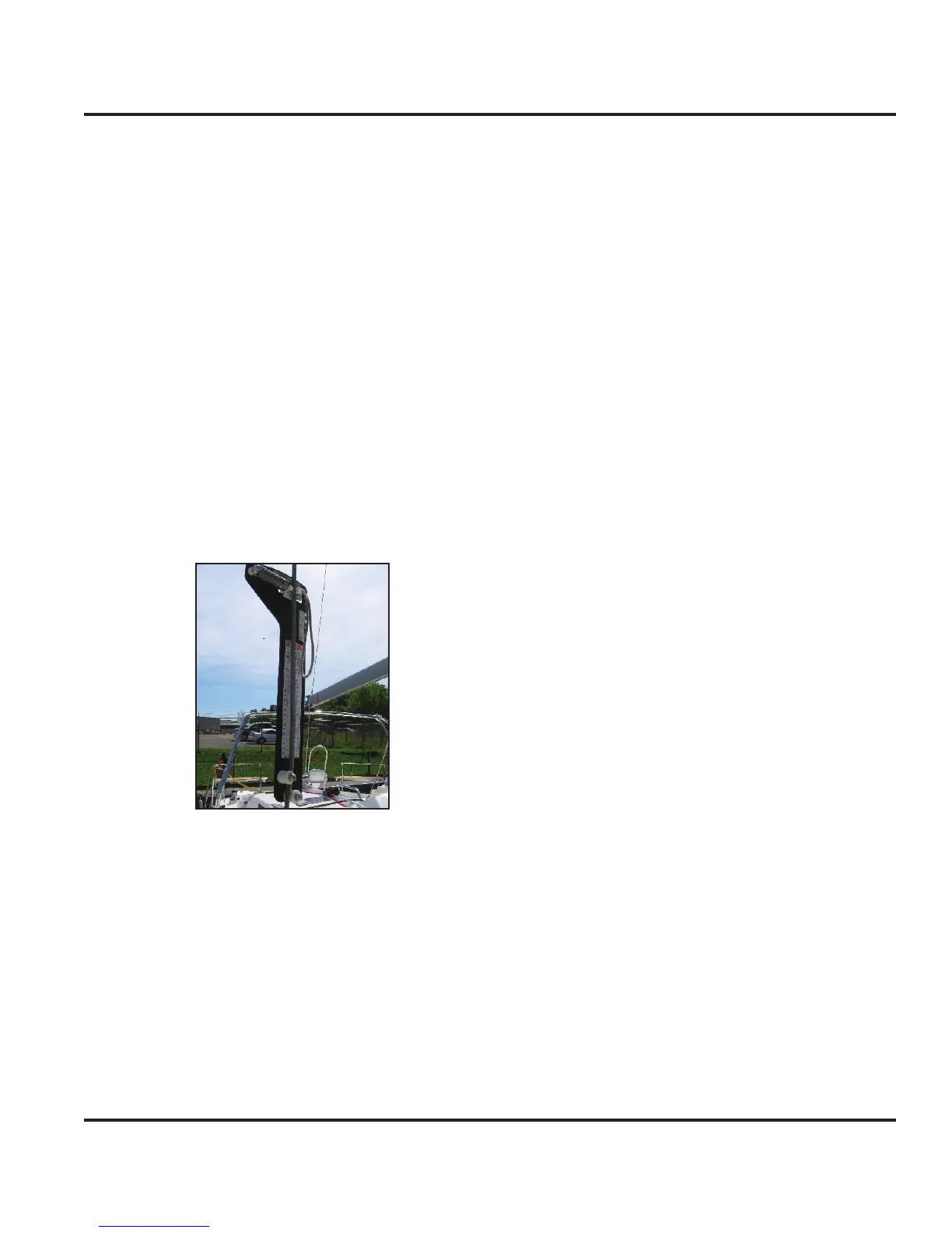
Using a tension gauge (Fig. 12.5), tension the outer
shrouds to 20% of their breaking load.
Disengage the crane strap (may require going aloft).
Relocate the boat away from the crane work area.
Figure 12.5
12.7.4 Tuning the Mast
Using a halyard, check that the mast is centered from
side to side by pulling it tight to one side and marking
the halyard next to the cap shroud chainplate.
Move to the opposite cap shroud chainplate and ver-
ify the mark is the same as the first.
If not, tighten or loosen the intermediate shrouds
equal amounts until the mast is centered.
Using a tension gauge, tension the V1s to 20%, D1s
to 15% and RDs to 12%-15% of their breaking load.
5.
6.
7.
8.
9.
10.
11.
12.
13.
1.
2.
3.
4.
12.7.4 Boom Installation
Man this procedure with at least one person on each
end of the boom.
Position the boom on the deck with forward end cap
immediately aft of the mast with aft end resting on the
arch (with traveler car track or sail cover slot facing
up).
Shackle the topping lift to the aft boom end cap and
raise the boom slightly. Verify or route the topping lift
as described in the Running Rigging section above.
Ensure someone holds the aft end of the boom to
stabilize against any sway.
Raise the forward boom cap to the gooseneck and
bolt the boom to the mast with the toggle.
Temporarily tie the boom’s aft end to the arch with
enough slack to allow installation of the vang.
12.7.5 Boom Outhaul Installation
Verify or route the boom outhaul line as described in
the Running Rigging section above (see also Figure
12.21 for furling rig and Figure 12.26 for standard
rig).
The outhaul should be routed through the inboard
starboard sheave position within the boom.
Lash the sail end of the outhaul to the aft boom end
until the mainsail is ready for installation.
12.7.6 Traveler Lines Installation
Verify or route both traveler lines as described in
the Running Rigging section above (see also Fig.
12.22).
Route the each line’s control ends through the port
and starboard cleat block.
12.7.7 Mainsheet Installation
Verify or route the mainsheet as described in the
Running Rigging section above (see also Figures
12.21 and 12.22).
The mainsheet should be routed through the out-
board starboard sheave position within the boom.
Route the control line through the single sheet stop-
per located on the port arch rail.
12.7.8 Vang Installation (Conventional & Solid)
1.
2.
3.
4.
5.
1.
2.
3.
1.
2.
1.
2.
3.