English-47
MAINTENANCE
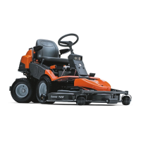
The cutting unit components
In the instructions below, a cutting unit with a rear
ejector is shown, but the same principles apply to
all cutting units unless otherwise stated.
The components mentioned are:
• A Catch
• B Inner pin
• C Catch guard
• D Handle
• E Height adjustment strut
• F Parallelism strut
• G Lowest height adjustment stop
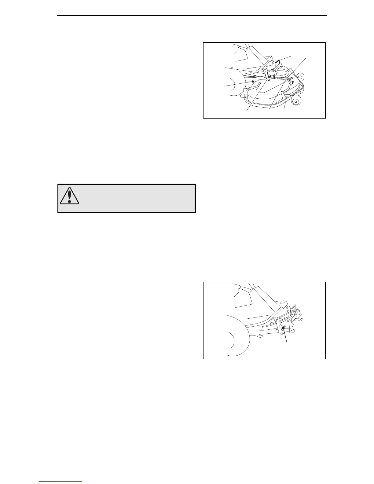
Attaching the cutting unit
Starting point for attaching the cutting unit:
• Place the machine on a flat surface.
• Lock the brake by pressing down the pedal and
locking with the push-button.
• Equipment hydraulics in the lower position (PF 21).
• Equipment frame in lowered position.
• Equipment frame locked with safety catch and locks
(A) in the inset position.
• Unit frame mounted on the cutting unit, see
“Removing the unit frame” on page 55.
8009-188
A
B
C
D
F
E
G
WARNING!
Exercise caution.
Risk of crush injuries
8009-022
A
A