English-36
DESIGN AND FUNCTION
Electrical System
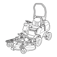
Component Locations
1. Headlight.
Equipped with H4 halogen lamps and adjustable headlamp insert.
2. Indicator panel.
Indicates different functions on the machine.
3. Control panel.
4. Circuit board.
Contains LEDs for trouble shooting.
5. Circuit fuses.
See the section “Fuses” on page 39.
6. Starter.
See the Perkins manual for component information.
7. Alternator.
See the Perkins manual for component information.
8. Engine temperature sensor.
See the Perkins manual for component information.
9. Oil pressure sensor (concealed). See the Perkins service manual for component information.
10. Fuses and main relay.
See the section “Fuses” on page 39.
11. Main fuse.
Melt fuse placed on the battery +pole
See the section “Fuses” on page 39.
12. Battery.
Maintenance free with service indication.
13. Magnetic coupling for power take-off.
Engages the cutting unit drive.
8009-888
Component locations Electrical System

 Loading...