HUST CNC H6D-B3 MANUAL
25
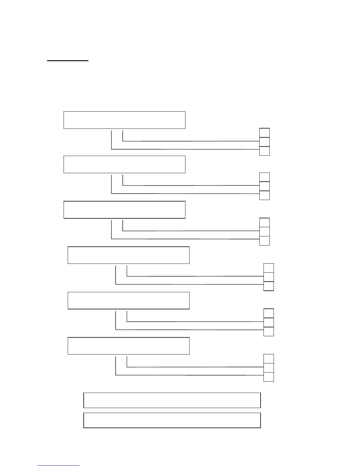
13. Machine Connection Diagram
Input Signal
(Input Board) Connect signal line to input board of HUST, and then connect to input
connector on the H3BN through DB25LF of the input board. Using HUST input
board has an advantage that it will protect the controller lines of H3BN series. This
connecting way is only suit for the input connector of NPN type
Fig 32
MPG connection:Plz check the MPG diagram.
EM-STOP:Plz check the Appendix 1
L-axis Limit(hardware+)
+24V
GND
I000
L-axis Limit(hardware-)
+24V
GND
I001
D-axis Limit(hardware+)
+24V
GND
I002
D-axis Limit(hardware-)
+24V
GND
I003
L-axis Home Limit
+24V
GND
I008
D-axis Home Limit
+24V
GND
I009