HUST CNC H6D-B3 MANUAL
28
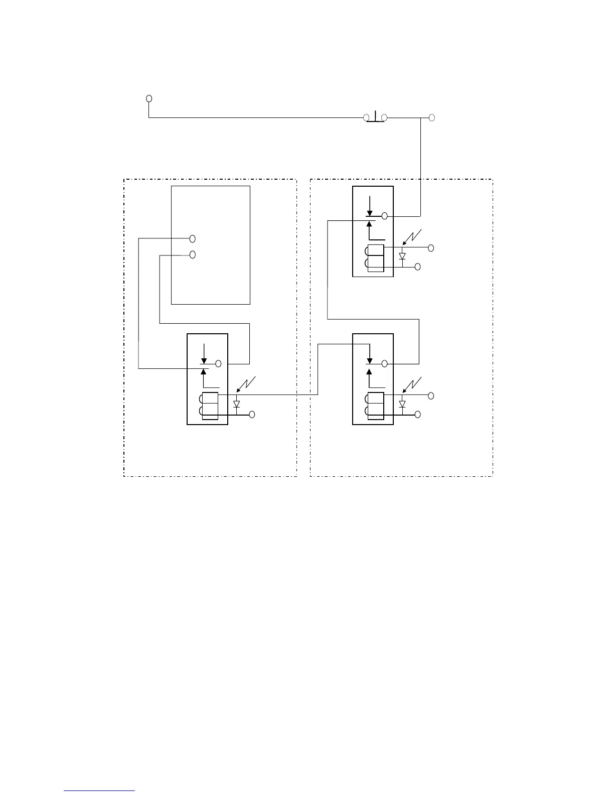
Appendix 1:Emergent Stop Connection Diagram
Fig 35 Emergent Stop Connection
PS :
1.
Relay A
、
B are protective lines for starting. They prevent the controller starting
failure. Output will destroy machinery construction.
2.
Relay C is servo-on relay.
3.
Relay A
、
B are two outputs in PLC.
4.
Relay C commonly is multi-joint. Each driver needs an unique joint. And some
drivers can’t.
5.
The PLC edition of servo-on is mentioned in appendix-3.
Spark Killer
Relay B
PLC
Output
24V
Spark Killer
Relay A
PLC
Output
24V
SERVO-DRIVER
Servo-On
Si