Installation and Maintenance Manual
10
slab
Roll pins line
up drive rail
segments to
assure perfect
splicing
fencepost shim as necessary
drive rail
drive rail
limit ramp
limit roller
limit switch
Installation
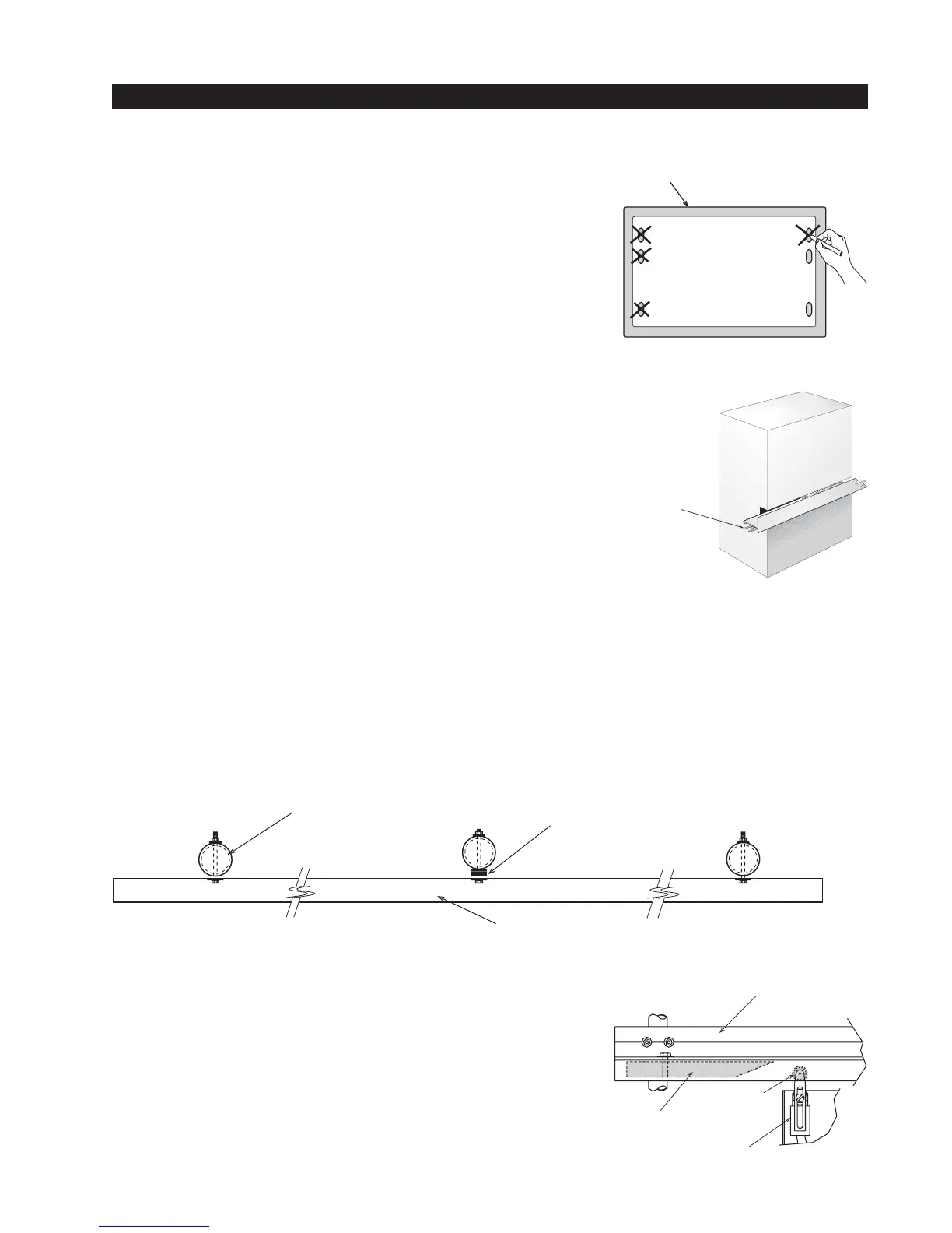
1. Drill four holes for concrete anchors
Each operator comes with a paper template with the anchor
slots. Place the template on the slab; making sure that it is
parallel to and 1 3/4" from the gate. Trace the slots, remove the
template, and then scribe the locations for your anchor bolts.
Drill holes for the anchor bolts in the center of the slots you
marked, so that you will have some room for adjustment. There
are six mounting slots in the chassis, install at least four 1/2 “ x
4” concrete anchor bolts, using two per side.
2. Line up the operator
Put the operator in position onto the anchor bolts. Verify that the
operator is parallel and 1 3/4" away from the gate on both the left
and right sides, and then tighten the anchors securely.
3. Two part Operators (battery models and 333 modular
models)
These two part operators come with a separate enclosure, which
should be mounted within 10 feet of the operator, but not more
than 100 feet. We recommend wall mounting or using two 4"
posts, with horizontal mounting strut to create a support for this
enclosure.
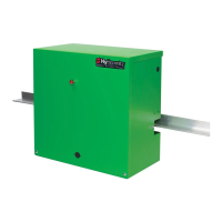
4. Bolt the Drive Rail to the Gate Panel
Connect multiple sections of drive rail together with 1/4" roll pins for a perfect splice. The drive rail
must be bolted to each vertical member of the gate panel. This may be done with U-bolt clamps or
through bolts, however U-bolt clamps allow for easy up down adjustment. If the gate is bent or
warped, shim the drive rail so that it is straight ± 1/4" throughout the travel of the gate. When the
drive rail has been installed at the correct height, the top surface is 9 3/4" above the operator base.
A label on each side of the operator indicates the correct height.
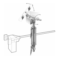
5. Install Limit Ramps on Underside of Drive Rail
Push the gate to the fully closed position and drill a 3/8" hole in
through the drive rail to mount a 12" plastic limit ramp under the
drive rail, in the wheel channel, at a location that will trip the
limit switch approx. 6" before the exact spot you want the gate
to stop. Adjust the lever arms on the limit switch so that the
roller clears the underside of the drive rail by at least 1/4 inch.
Push the gate fully open and repeat this procedure with the
other limit ramp. See the Drive Rail drawing S22 on page 16.