Installation and Maintenance Manual
45
Smart Touch Controller
LIMIT
SENSORS
DUAL GATE
RS485
RADIO OPTIONS
L R RPM COM A B COMOPEN+24V +24VEDGECOM
4
RS23216
black
gray
gray
red
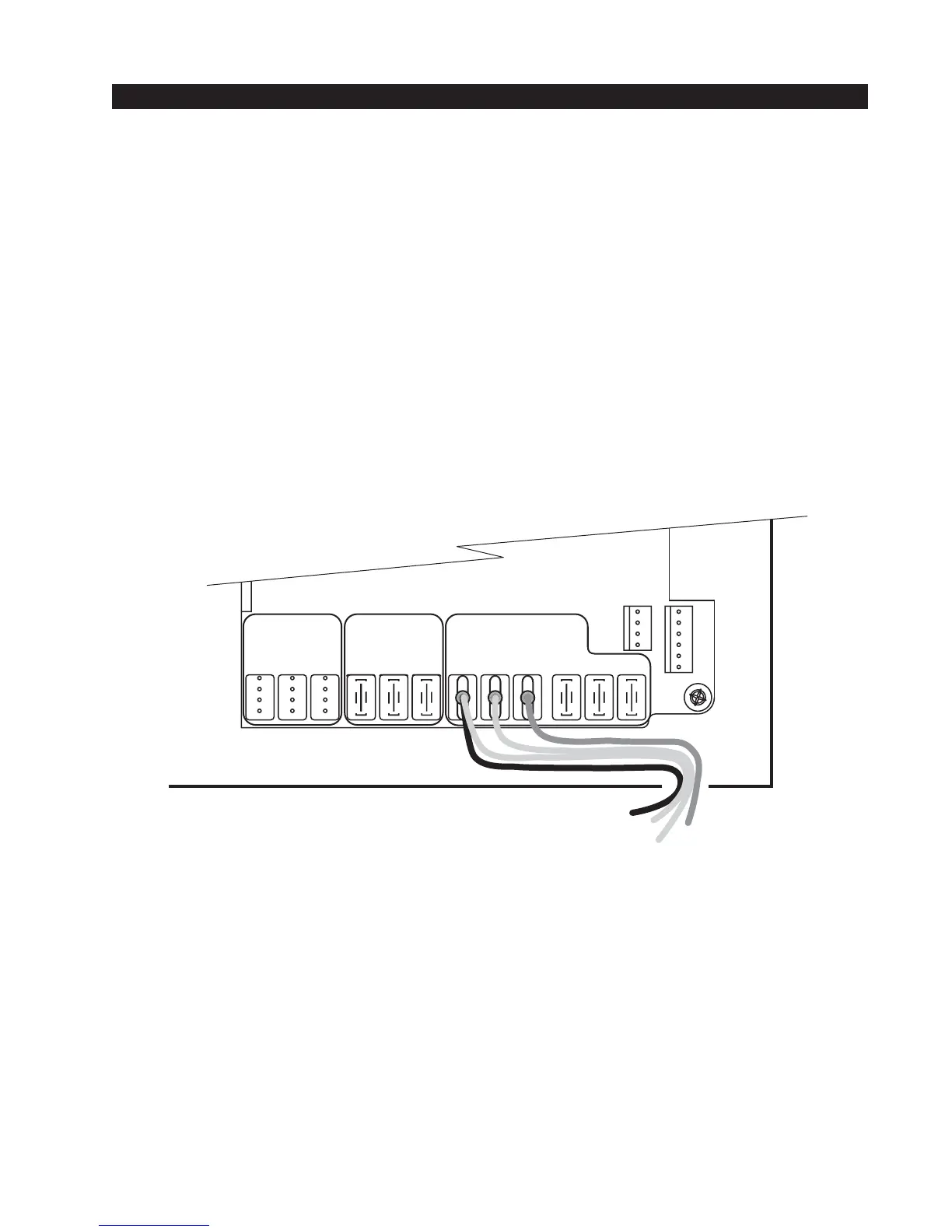
Connecting a Radio Receiver
Mount a commercial style 24-Volt radio receiver (external antenna type) on the inside of the opera-
tor, below the electrical box. Knock out the smallest hole in the lower right corner of the electrical
box and route the wires to the area marked Radio Options. Only three wire connections are
needed because the 24-Volt supply and the radio output share a wire. Being certain to observe
polarity, crimp the black radio power wire together with one of the radio output wires into a .25"
spade connector and connect to the COM terminal. Connect the red wire to the +24V terminal and
connect the other radio output contact wire to the spade marked OPEN. Note that this terminal is
the same as the #4 input terminal labeled Edge Sensor on the main control board.
Mount an external antenna onto the top of a fixed post of the fence near the operator.
Connect the antenna into the socket on the radio receiver.
Set the DIP switches in the receiver to match the same code used in the transmitter.
If there is also to be an edge sensor transmitter to reverse the gate, be certain to use a two channel
commercial receiver. Remember that each transmitter and receiver must have their codes set the
same or they will not function.
Radio output wires