Installation and Maintenance Manual
47
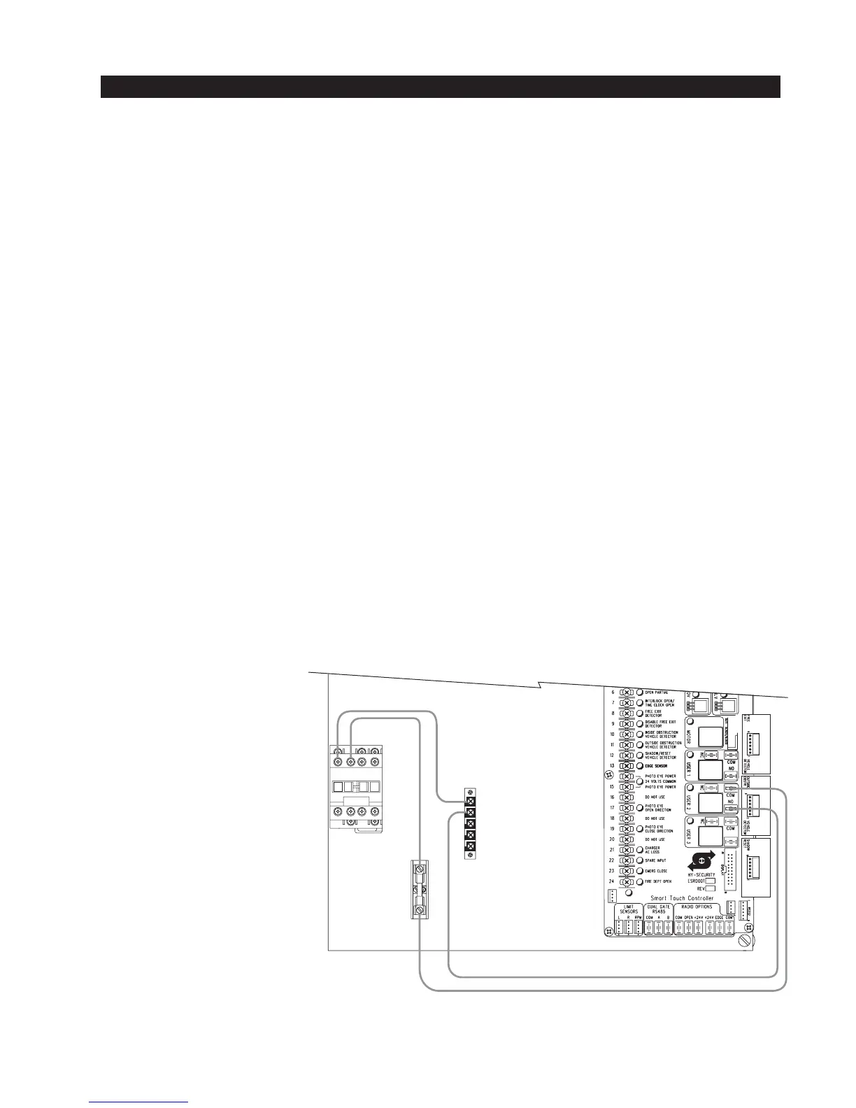
LOCK
LOCK
COM
NO
NC
15A FUSE
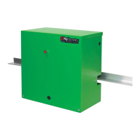
CONTROL
BOARD
CONTACTOR
L1 L2
Solenoid Lock Instructions - Internal Type
Internal Solenoid Lock Description:
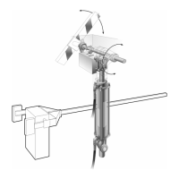
Hy-Security offers an optional internal solenoid deadbolt lock that employs a 3/4" stainless steel
lock pin that fits into a notch cut into the drive rail. The lock solenoid is voltage specific for 120V,
208V, 230V or 480V, therefore be certain that if the operator voltage is modified that the solenoid is
also changed. An internal indicator switch is also provided which may be required in some installa-
tions in order to verify whether the deadbolt is in the locked or unlocked position.
Activation of a Solenoid Deadbolt Lock:
A solenoid lock must be activated prior to any gate motion or the gate will bind the lock mechanism.
Hy-Security’s internal lock must also remain engaged until the soft stop time cycle is complete at
the end of travel. To provide the solenoid lock logic requirement, one of the three user relays
(typically user relay 2) must be set to function #6 and wired to supply power to the lock solenoid.
The same relay function can easily be used to drive an external solenoid lock device as well.
Adjustment of the Factory Solenoid Lock:
Operators equipped with our factory solenoid lock require a notch to be cut into the outer vertical
face of the drive rail. The notch location is determined in the field after the gate operator is func-
tioning properly. Run the gate to its full closed position and note the location where the deadbolt pin
strikes the drive rail. Mark for a 3" wide slot in the rail with the lock pin in the center. Make two cuts
with a hacksaw and break out the notched section. Operate the gate a few times to verify that the
deadbolt always enters the notched area.
The lock enclosure itself may need to be adjusted so that the lock pin strikes in the center of the
vertical edge of the drive rail. The face of the lock enclosure is slotted to accommodate this adjust-
ment. With a 1/2" open end wrench, loosen the two bolts retaining the lock enclosure and move the
enclosure up or down to achieve the correct adjustment.
Electrical:
When the factory pre-
installs the internal solenoid
deadbolt lock, a five pole
terminal strip is added. Two
terminals are the high
voltage to the solenoid and
the remaining three are the
output of the lock position
indicator switch. If needed
for interlocking or indicator
lights, wire accordingly to
the terminals labeled: COM,
NO and NC.